American Fibertek MR-81 User Manual
Page 3
3
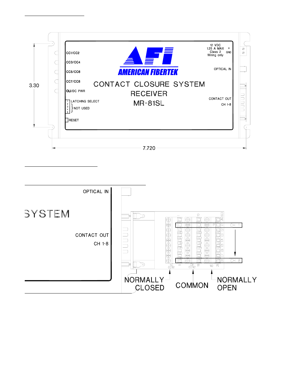
POWER CONNECTION
Power is supplied to the unit via a two pin terminal connector on the right side of the unit. See label on
unit for proper location of input power.
FIBER INPUT CONNECTION
The optical input connection is made via a FC/PC connector located on the right side of the unit.
CONTACT CLOSURE OUTPUT CONNECTIONS
Contact closure output connections are made via terminal blocks attached to the right side of the unit.
Please note that the three Channel 1 output connections begin at the second terminal screw closest to
the fiber connection on each of the three nine pin terminal strips. Channels 2 through 8 connections
continue down the terminal strip. Each channel has one common output connection that can be used
with a normally closed connection or a normally open connection. For optimum performance the copper
cables carrying the contact closure signal should be the shortest length of wire practical.
- MT-81 (4 pages)
- RR-81 (4 pages)
- MR-88 (4 pages)
- MT-88 (4 pages)
- MTX-81B (4 pages)
- RRX-81B (4 pages)
- MR-81SL (4 pages)
- MT-81SL (4 pages)
- RD-20D AFINETY (12 pages)
- DRBK-1 (4 pages)
- PSR-2 (4 pages)
- SR-20 (4 pages)
- SR-20 R (7 pages)
- SR-20D (4 pages)
- MTX-8406C (5 pages)
- MTX-8410C (8 pages)
- MTX-8410C-SL (8 pages)
- MTX-8423C (8 pages)
- MTX-8423C-SL (8 pages)
- MTX-8485C (12 pages)
- MTX-8485C-SL (12 pages)
- MTX-8489C (12 pages)
- MTX-8489C-SL (12 pages)
- MRT-880C-SL (4 pages)
- MRT-880C (4 pages)
- MRT-860SL (8 pages)
- MRT-860 (8 pages)
- RT-440C-SL (4 pages)
- RR-440C-SL (4 pages)
- MT-440C-SL (4 pages)
- MR-440C-SL (4 pages)
- MR-440C-E (4 pages)
- MT-440C-E (4 pages)
- RR-440C-E (4 pages)
- RT-440C-E (4 pages)
- MR-440C (4 pages)
- MT-440C (4 pages)
- RR-440C (4 pages)
- RT-440C (4 pages)
- MR-404C (4 pages)
- MT-404C (4 pages)
- RR-404C (4 pages)
- RT-404C (4 pages)
- MR-220C (4 pages)