Led indicators, Unit connectors, Led indicators unit connectors – Axis Communications 209MFD-R M12 User Manual
Page 14
Page 14
AXIS 209FD/FD-R/FD-R M12/MFD/MFD-R/MFD-R M12 Installation Guide
LED indicators
Unit connectors
(AXIS 209FD/AXIS 209MFD) Network connector - Female RJ-45 Ethernet connector for
10BaseT/100BaseTX. Supports Power over Ethernet. Using shielded cables is recommended.
(AXIS 209FD-R/AXIS 209MFD-R) Network connector - Rugged female RJ-45 connector.
Supports Power over Ethernet. Using shielded cables is recommended
(AXIS 209FD-R M12/AXIS 209MFD-R M12) Network connector - Rugged male M12
Ethernet connector. Supports Power over Ethernet. Using shielded cables is recommended.
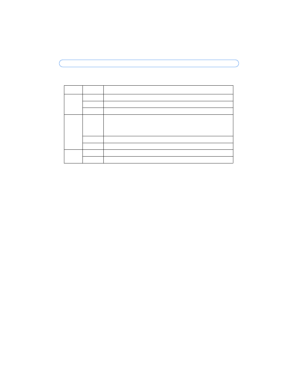
LED
Color
Indication
Network
Green
Steady for connection to a 100 Mbit/s network. Flashes for network activity.
Amber
Steady for connection to 10 Mbit/s network. Flashes for network activity.
Unlit
No network connection.
Status
Green
Steady green for normal operation.
Note: The Status LED can be configured to be unlit during normal operation, or to
flash only when the camera is accessed. To configure, go to
Setup > System
Options > LED settings. See the online help files for more information.
Amber
Steady during startup, during reset to factory default or when restoring settings.
Red
Slow flash for failed upgrade.
Power
Green
Normal operation.
Amber
Flashes green/amber during firmware upgrade.