Wiring diagram, Figure a – Advent ADV38 User Manual
Page 9
9
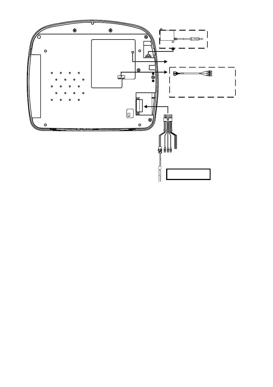
1) Make the connections to the vehicle for the 12 pin wiring harness.
2) Connect the 2 pin power harness to vehicle’s electrical system by
tapping into an accessory hot line and a good ground.
3)
Connect the 12 pin power/signal harness to the mating connector
on the video monitor.
4) Connect the 2 pin connector on the power harness to the 2 pin
connector on the power/signal harness.
5) Verify all functions of the system before final mounting of the
finished assembly.
A/V Source Definitions:
1. DVD - Built in DVD
2. USB - Built in USB
3. AV1 - Supplied 12 Pin Power / Signal Harness to 3 RCA Jack Pigtail is used for
AV1 input.
4 . AUX - AUX input.
5. GAME - Built in Game
*NOTE: If the optional relay box is P/N SIRSWB installed, it recommended that the antenna for
the FM modulator antenna wire is unplugged. See ADV38 Wiring Diagram (Figure A) for
antenna location.
**NOTE: Extending the wireless antenna beyond its 12 inch length will cause the FM
modulator to exceed FCC limits of wireless transmission. When installing the unit position the
antenna for best reception.
***NOTE: Plug in 12 pin AV Adapter cable when connecting to an external source (i.e. game
controller, etc).
WIRING DIAGRAM
* Antenna for Wireless FM Mod.
** See Antenna Note
* Relay Box (OPTIONAL)
SIRSWB
L
in
e
O
u
t-
R
(
R
e
d
)
L
in
e
O
u
t-
L
(
W
h
it
e
)
L
in
e
O
u
t-
V
(
Y
e
llo
w
)
Auxiliary Video Display
12 Pin Power /
Signal harness
2 Pin Power
Wire Harness
with choke
Figure A
Dome Light
Power source
12 Pin AV
Adapter Cable
AV1 Input
***
AV OUTPUT