A.O. Smith 186589-004 User Manual
Page 16
16
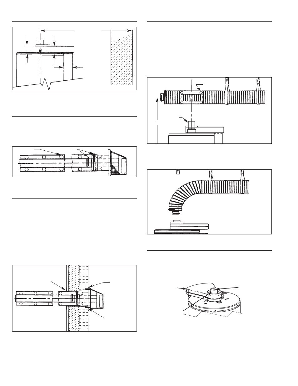
STANDARD VENT ARRANGEMENT
2.6 in.
(67mm)
3.6 in.
(91mm)
2.1 in.
(54.5mm)
WALL
17 in. (432mm) MIN.,*
80 in. (2.03m) MAX.
FIGURE 17
* If the horizontal distance is less than 760mm (30 in.), the
restricter plate must be installed (see Figure 22).
VENT ASSEMBLY
The vent tube and terminal can be assembled as shown in
Figure 18. There are springs fastened inside the corrugated
tube. When the vent tubes are pulled to a required length, the
springs will still be equally spaced.
CLAMP
SPRING
FIGURE 18
SECURING VENT TERMINATION ASSEMBLY TO THE
EXTERIOR WALL.
Some models are supplied with trim plates which may be used to
cover the holes in the wall (see Figures 1 and 19). Slide one trim
plate (if supplied) over the outer corrugated tube, then insert the
outer corrugated tube through the clearance hole from exterior
wall. Secure the trim plate to the exterior wall, then secure the
vent terminal to the exterior wall with 4 screw anchors (included)
appropriate for the type of wall construction. Caulk the junction
of the vent terminal base plate and the exterior wall with exterior
type sealant (not included). Slide the trim plate (inside) over the
outer corrugated tube and fasten the trim plate to the interior
wall. Caulk the junction of the outer corrugated tube and the trim
plate (inside) with suitable sealant.
SEALANT
TRIM PLATE
(INSIDE)
TRIM PLATE
(OUTSIDE)
FIGURE 19
UNCOMPRESSING THE CORRUGATED TUBING
1. Pull the inner corrugated tube towards the water heater
and leave some length over the water heater’s center for
bending.
2. Pull the outer corrugated tube toward the water heater and
leave it 25mm (1 in.) shorter than the inner corrugated tube.
3. Make sure there are two springs evenly spaced at the bend in
the tube.
4. Use metal hangers to keep venting level or with a slope
upward from the heater to terminal.
REDUCER
SPRING
H
FIGURE 20
Bend both the corrugated tubes toward the water heater’s fl ue
connection.
FIGURE 21
VENT RESTRICTER PLATE
For short horizontal vent runs (see Figure 17) place the restricter
plate over the fl ue tube reducer before connecting the inner cor-
rugated tube to the fl ue tube reducer. DO NOT use the restricter
plate if the horizontal run is greater than 760mm (30 in.).
RESTRICTER
PLATE
FLUE TUBE
REDUCER
UPPER AIR
INLET BOX
FIGURE 22
Pull and connect the inner corrugated tube to the water heater’s
fl ue tube reducer with hi-temp red silicone (included) and gear
clamp. Make sure this connection is tight and leak proof.
*The sealant between inner corrugated tube and water heater’s
fl ue tube reducer must be hi-temp red silicone or other material
suitable for 315°C (600°F) continuous service.