Diagram 3: connector pinouts, Distribution amplifiers – Altinex Distribution Amplifier DA1506RT User Manual
Page 7
DISTRIBUTION AMPLIFIERS
400-0016-004
6
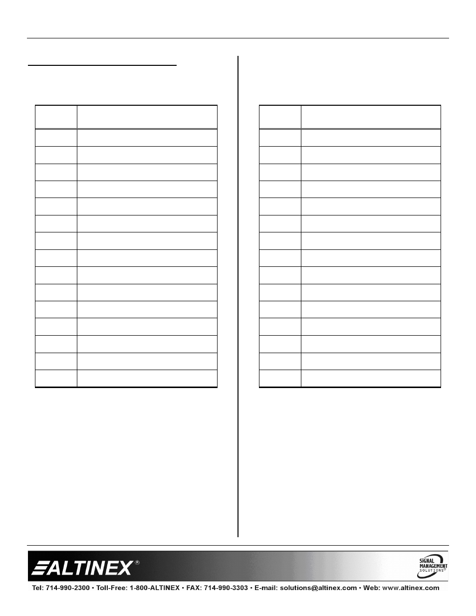
DIAGRAM 3: CONNECTOR PINOUTS
INPUT CONNECTORS
Pin No.
PIN ASSIGNMENTS
1
Red
2
Green
3
Blue
4
Ground
5
Ground
6
Ground
7
Ground
8
Ground
9
VESA +5V IN
10
Ground
11
Ground
12
VESA SDA
13
Horizontal Sync
14
Vertical Sync
15
VESA SCL
Table 4. The DA1506RT Input Pins
OUTPUT CONNECTORS
Pin No.
PIN ASSIGNMENTS
1
Red
2
Green
3
Blue
4
No Connection
5
Ground
6
Ground
7
Ground
8
Ground
9
+5V
10
Ground
11
No Connection
12
No Connection
13
Horizontal Sync
14
Vertical Sync
15
No Connection
Table 5. The DA1506RT Output Pins