External equipment setup, Hd receiver setup, Component connection – LG 37LD325H User Manual
Page 22: How to connect, How to use, Connect the video outputs (y, p, Blue, and p, Red)
EXTERNAL EQUIPMENT SETUP
EX
TE
R
N
A
L
EQ
U
IP
M
EN
T
S
ET
U
P
22
HD RECEIVER SETUP
ꔛ
To prevent the equipment damage, never plug in any power cords until you have finished connecting all
equipment.
Y, C
B/
P
B
, C
R/
P
R
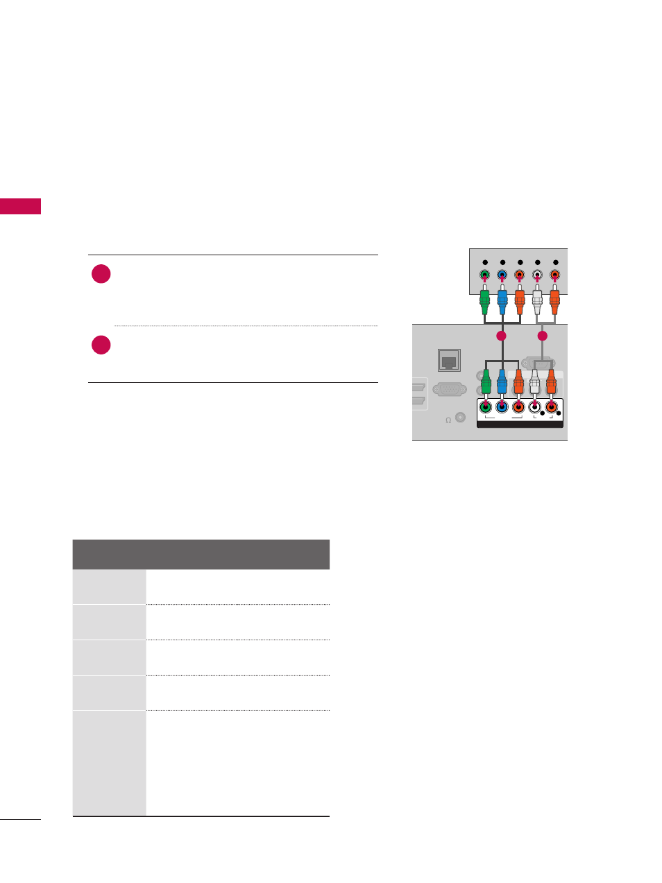
1. How to connect
1
Connect the video outputs (Y, P
B
, P
R
) of the
digital set-top box to the
COMPONENT IN
VIDEO jacks on the TV. Match the jack colors (Y
= green, P
B
= blue, and P
R
= red).
2
Connect the audio output of the digital set-top
box to the
COMPONENT IN AUDIO jacks on
the TV.
2. How to use
ꔛ
Turn on the digital set-top box.
(Refer to the owner’s manual for the digital set-
top box operation.)
ꔛ
Select the
Component
input source on the TV
using the
INPUT
button on the remote control.
Component Connection
This TV can receive digital over-the-air/digital cable signals without an external digital set-top box.
However, if you do receive digital signals from a digital set-top box or other digital external device.
Resolution
Horizontal
Frequency(kHz)
Vertical
Frequency(Hz)
720x480i
15.73
59.94
15.73
60.00
720x480p
31.47
59.94
31.50
60.00
1280x720p
44.96
59.94
45.00
60.00
1920x1080i
33.72
59.94
33.75
60.00
1920x1080p
26.97
23.976
27.00
24.00
33.71
29.97
33.75
30.00
67.432
59.94
67.50
60.00
EXTERNAL EQUIPMENT SETUP
ANTENNA/
CABLE IN
RGB IN (PC)
AUDIO IN
RGB/DVI
REMOTE
CONTROL
OUT
AV IN
RS-232C IN
(SERVICE ONLY)
VIDEO
AUDIO
L(MONO)
R
AUDIO IN
RGB/DVI
REMOTE
CONTROL
OUT
VIDEO
AUDIO
Y
P
B
P
R
L
R
COMPONENT IN
Y
L
R
P
B
P
R
ANTENNA/
CABLE IN
RGB IN (PC)
COMPONENT IN
AV IN
RS-232C IN
(CONTROL&SERVICE)
VIDEO
AUDIO
L(MONO)
R
VIDEO
AUDIO
Y
P
B
P
R
L
R
HDMI OUTPUT
ANTENNA/
CABLE IN
RGB IN (PC)
AUDIO IN
RGB/DVI
COMPONENT IN
AV IN
RS-232C IN
(CONTROL&SERVICE)
VIDEO
AUDIO
L(MONO)
R
VIDEO
AUDIO
Y
P
B
P
R
L
R
L
R
AUDIO
DVI OUTPUT
/DVI IN
1
2
SPEAKER
OUT(8 )
RJP
AUDIO IN
RGB/DVI
REMOTE
CONTROL
OUT
SPEAKER
OUT(8 )
RESET UPDATE
RESET UPDATE
2
1
/DVI IN
RJP
REMOTE
CONTROL
OUT
2
1
/DVI IN
SPEAKER
OUT(8 )
RJP
RESET UPDATE
1
2