Control panel – AmpliVox SW227 User Manual
Page 3
3
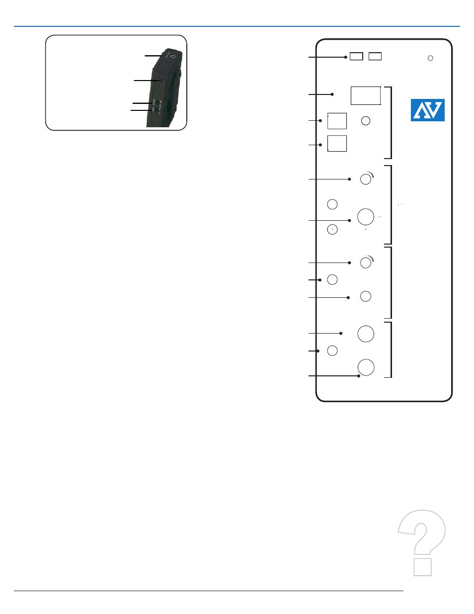
SW227
COnTROL PAnEL
main power
switcH
internal wireless
mic receiVer
master VolUme
micropHone inpUts
line in
line oUt
**connect s1670
Here
speaKer jacK
speaKer jacK
tone control
aUXiliarY VolUme
power inpUt
aUX oUt
either A or B. Both the microphone transmitter and the amplifier have
to be on the same frequency for the wireless mic to work proplerly. If
you encounter interference, switch frequencies. Rotate VOLUME control
knob on the amplifier to obtain desired loudness level throughout the
coverage area.
The microphone has an on/oFF switch. it should always be in the OFF
position until the main power is ON and you are ready to speak.
The VHF wireless microphone system is compact, lightweight and
compatible with all AmpliVox VHF wireless systems. The wireless mic
operates in an authorized VHF band and has a useful range of up to
200-ft. in line-of-sight applications. Each system operates on two crystal-
controlled, switch selectable frequencies for clear clean transmission.
“a” channel
“b” channel
t6: 171.105 mHz t7: 171.845
wireless mic set Up
The frequency appears on the back of each unit. Both transmitter and
receiver must have the same, and both units must be set to either “A” or
“B.” Note that two transmitters on the same frequency will not work with
one receiver. However two or more receivers will work with the same
transmitter. Before use, make certain you understand the function and
operation of the system.
main power switcH
The main power switch is located on the control panel. Flip the rocker
switch to the ON position. The red light next to the switch will light up
showing that the power is on.
dc inpUt
Connection for an optional external power adapter.
aUX oUt
Power source for 12 to 15V DC accessories.
master VolUme
Controls the volume level of the microphones, including the wireless
microphones.
micropHone inpUts
There are three microphone inputs, which can be used simultaneously:
dYnamic
- for standard dynamic microphones, 1/4 in.
condenser
- for electret or condenser microphones, which require
phantom power (supplied from the amplifier) 3.5 mm
wireless
- accepts output from an external wireless microphone
receiver
aUXiliarY
The line in provision is for connecting an external audio source such
as a CD player, tape player, MP3 player or computer sound card This
input also serves as a provision for connecting additional wireless
microphone receivers, audio mixers and other line level audio sources.
Separate VolUme and tone control knobs allow flexibility in controlling
the sound quality as well as balancing the auxiliary source with the
microphones.
NEED HELP?
caLL 800-267-5486
or 847-498-9000
EmaiL:
cuStomErSErvicE@
amPLi.com
P
OW
E
R
M
I
C
RO
P
H
O
N
E
A
U
XI
L
I
A
R
Y
O
U
T
P
U
T
FREQ PWR
INTERNAL
WIRELESS
RECEIVER
ON
A B OFF ON
ON
OFF
ON
DC IN
AUX OUT
CONDENSER
WIRELESS
DYNAMIC
VOLUME
VOLUME
LINE IN
TONE
SPEAKERS
LINE OUT
L
R
2
3
1
MADE IN USA
1-800-267-5486 WWW.AMPLI.COM
A
M
P
L
I
V
O
X
EXTEND YOUR
VOICE WITH
PORTABLE
SOUND
SYSTEMS
transmitter
mic inpUt jacK
power on indicator
power on/oFF switcH
cHannel selector switcH
oUtpUt
The line oUt provision may be used for connecting to an input on
a recording device, such as a computer sound card, MP3 recorder,
tape recorder, or similar device. The line oUt can also be used for a
number of other applications, such as connecting to a house system, or
connecting to one of our wireless speaker transmitters, for example.
eXternal speaKers
Two separately amplified speaker jacks allow you to use one or two
S1201, S1290, or any of our horn speakers for additional sound power.
Note: when using a stereo aUX source with
a single speaker, only one of the stereo
channels will be heard. However, all MIC
inputs are heard equally on both channels.
rF interFerence
Please note that wireless frequencies are
shared with other radio services. According
to the Federal Communications Commission
S
W
2
2
5