页面 8, Connection diagram, Host unit – Myron&Davis NV7TVZ1 User Manual
Page 8
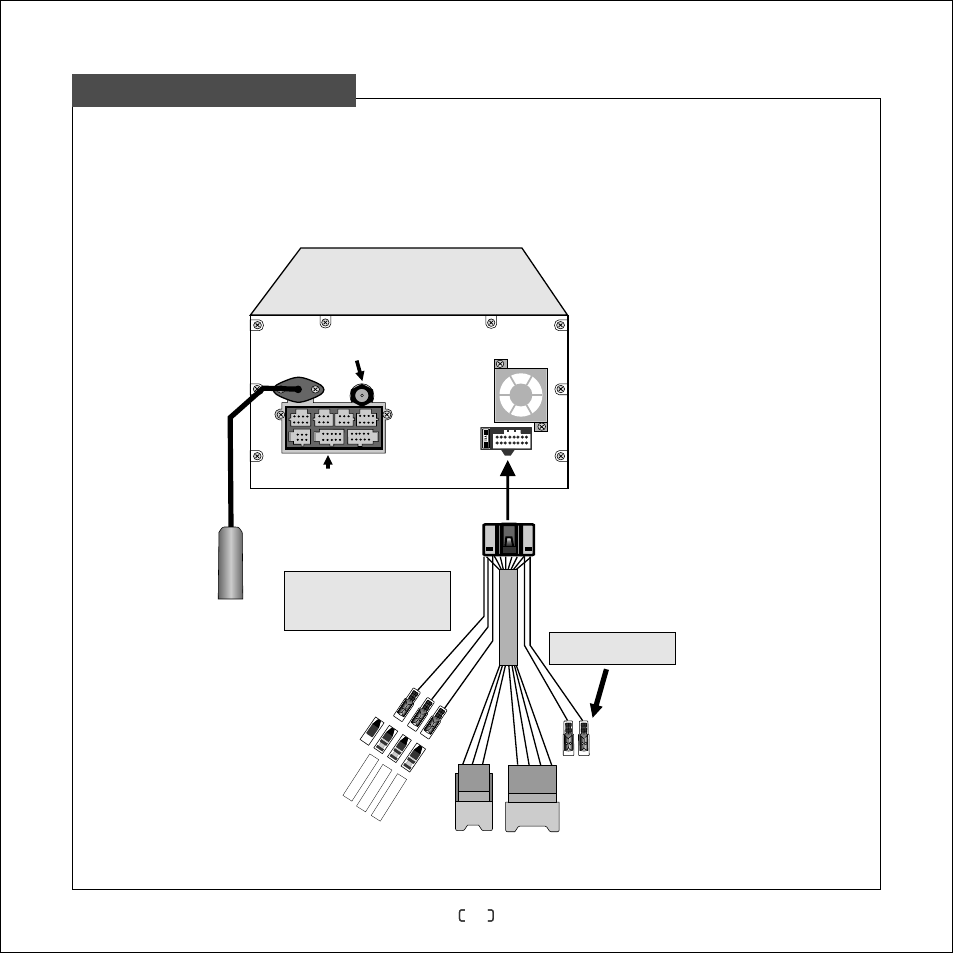
To ensure system functions properly, connect the wires according to the wiring diagram.
In order to prevent short circuit, cover the insulation casings of audio and video when not
used.
6
Multi-function compound interface
Radio antenna
Built-in navigation
antenna interface
Built-in TV
antenna interface
Connection Diagram
GPS-ANT
TV-ANT
Host Unit
CD
C
T
B
AT
CD
C
AC
C
CD
GN
C
D
Blue
CDC BATT
:
Red:CDC ACC(
)
Not connected
Black:CDC GND
Connected to power supply socket of the original car
Blue:
Blue
/White
:Handbrake
power loudspeaker
wire
Reverse