ACTiSYS ACT-IR100S User Manual
Page 8
&'
(
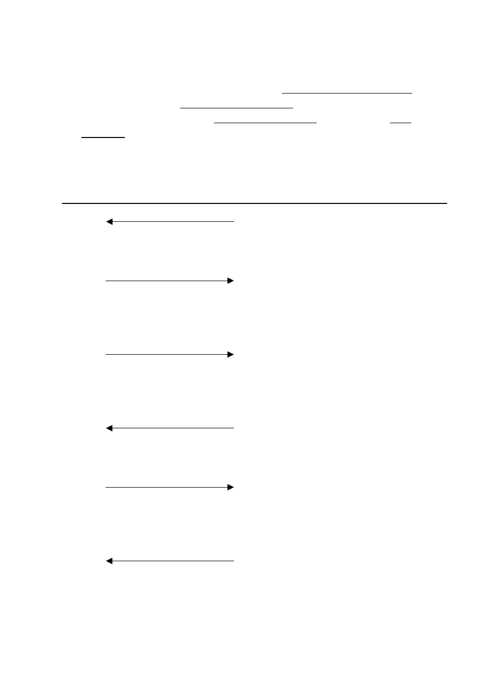
● Serial Port: When connecting modems etc. to the Data Communication Equipment
(DCE) side, connect the corresponding signal names of the modem and IR100S+.
When connecting to PC’s to the Data Terminal Equipment (DTE) side use a cross
connection for IR100S+ and the PC or Plotter/Printer(with RS232 port).
Example Connection Reference #1: Modem (DCE) Connection
IR100S+ I/F
< Straight Cable >
Modem(DCE)
RxD
RxD : Data Receiving
RD RD
Only valid with received data
when the DCD (CD) signal is on.
TxD
TxD : Data Transmission
SD
SD
Valid with sending data when
RTS (RS), CTS (CS), DSR (DR),
DTR (ER) are on.
/DTR
/DTR : Data Terminal Ready
ER
ER
Turns on when receiving and
transmitting of data is possible
and when the terminal has power.
/DSR
/DSR : Data set ready
DR
DR
Turns ON when the modem
is able to send and receive.
/RTS
/RTS : Transmission Request
RS
RS
Instructs the modem to be in
transmission mode. The terminal is
turned on before the transmission.
/CTS
/CTS : Transmissible
CS
CS
Indicates that the modem is able to
transmit. When CS is ON the
modem is able to receive.