Connecting the power and led, Connecting the usb ports – Antec NEW SOLUTION NSK 1380 User Manual
Page 3
2
3.
This case comes with three brass standoffs and three clip-on standoffs
preinstalled for easy installation. Line up the holes on your motherboard with
the standoffs, to install the motherboard slide the board towards the rear of
the case until the hook on each of the clip-on standoffs “clipped” the holes on
the motherboard.
Note: Not all motherboards will match with all of the provided screw holes,
and this is not necessary for proper functionality.
4. Remove the motherboard by lifting it up.
5.
Remove any of the pre-installed standoffs that aren’t needed. Insert any extra
clip-on standoffs in your tool bag onto the holes should your motherboard
require it.
6. Place the motherboard back on the standoffs.
7.
Fasten the motherboard to the rest of the standoffs with the provided Philips-head
screws. The motherboard is now installed.
Connecting the Power and LED
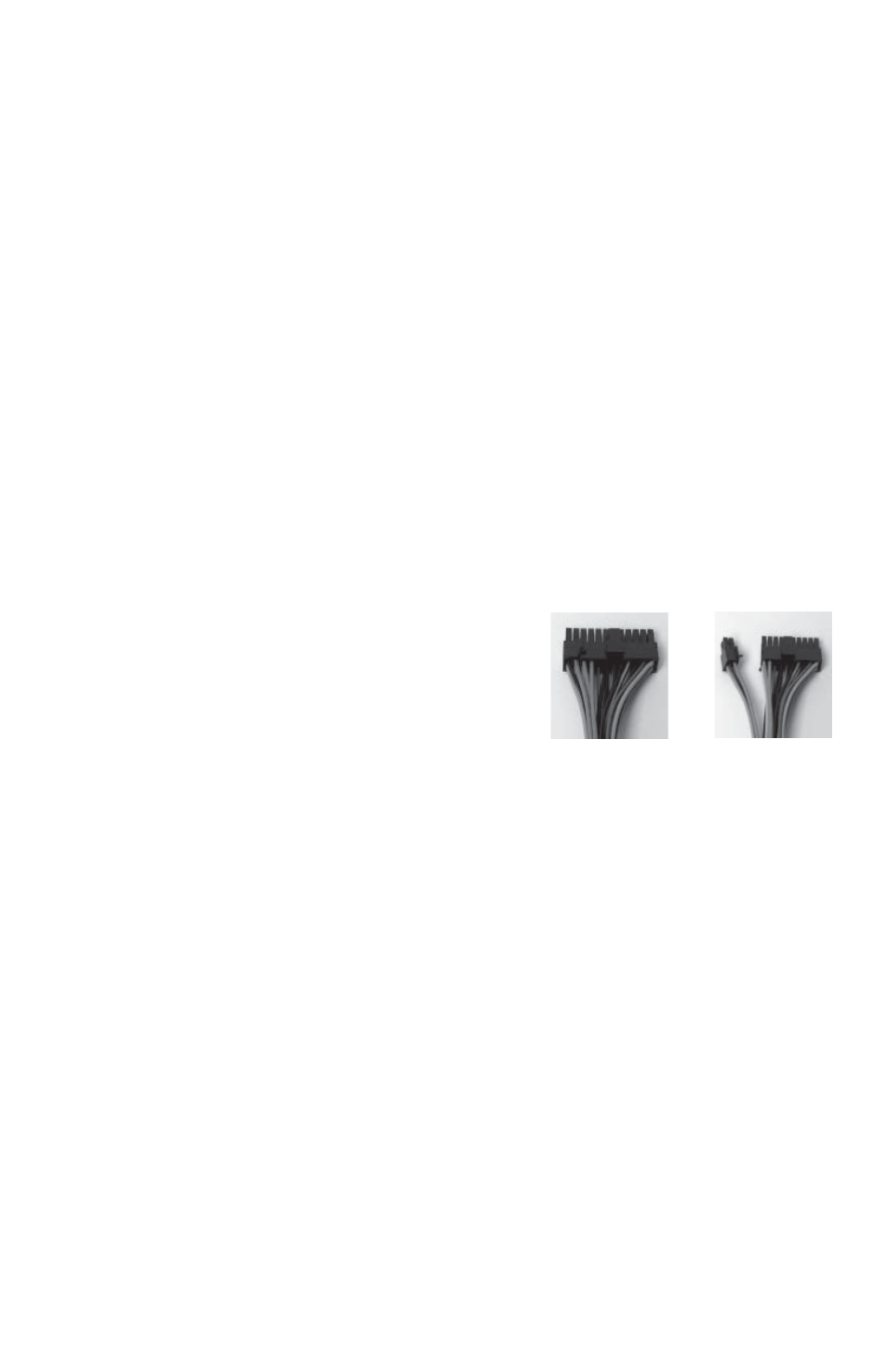
The power supply conforms to the ATX12V Version 2.01 standard. If the motherboard
has a 20-pin power receptacle, detach the 4-pin attachment on the 24-pin power
connector, see pictures 1 and 2. Before you connect the power supply to any of
the devices, please consult the appropriate user manuals for the motherboard and
other peripherals.
1.
Connect the 24-pin Main Power Connector and
the 4-pin connector to the motherboard
as needed. If the motherboard uses a 20-pin
connector, detach the 4-pin attachment on
the 24-pin power connector (see pictures 1
and 2).
Note: the detachable 4-pin section cannot
be used in place of a 4-pin+12V connector.
2.
Power Switch (labeled POWER SW) connects
to the PWR connector on the motherboard.
Polarity (positive and negative) does not matter for switches.
3.
Connect the Reset switch (labeled RESET SW) to the motherboard at the
RST connector.
Connecting the USB Ports
You will find a single 10-pin connector on a cable attached to the front USB ports.
This Intel standard connector is keyed so that it can’t be accidentally reversed as
long as it is connected to a proper Intel standard motherboard header. Connect the
10-pin connector to the motherboard headers so that the blocked pin fits over the
missing header pin.
Picture 1
Picture 2
For 24-pin
motherboards
For 20-pin
motherboards