Appendix c - in service test, Background information, C.1 frame structure – American Telecom AM64/128A User Manual
Page 47: C.2 in service test facilities
Appendix C - In Service Test
AM64/128A User Manual
A-8
APPENDIX C - In Service Test
BACKGROUND INFORMATION
The information passing between master and slave BBM’s comprises of user data and control data; the
latter is used for controlling and supervising the operation of the transmission system. In order that these
components can be separated the composite data is transmitted in frames with a fixed framing pattern to
identify the frame boundary. Data is transferrred at 71.1 kbps at the high rate and 142.2 kbps at double
rate.
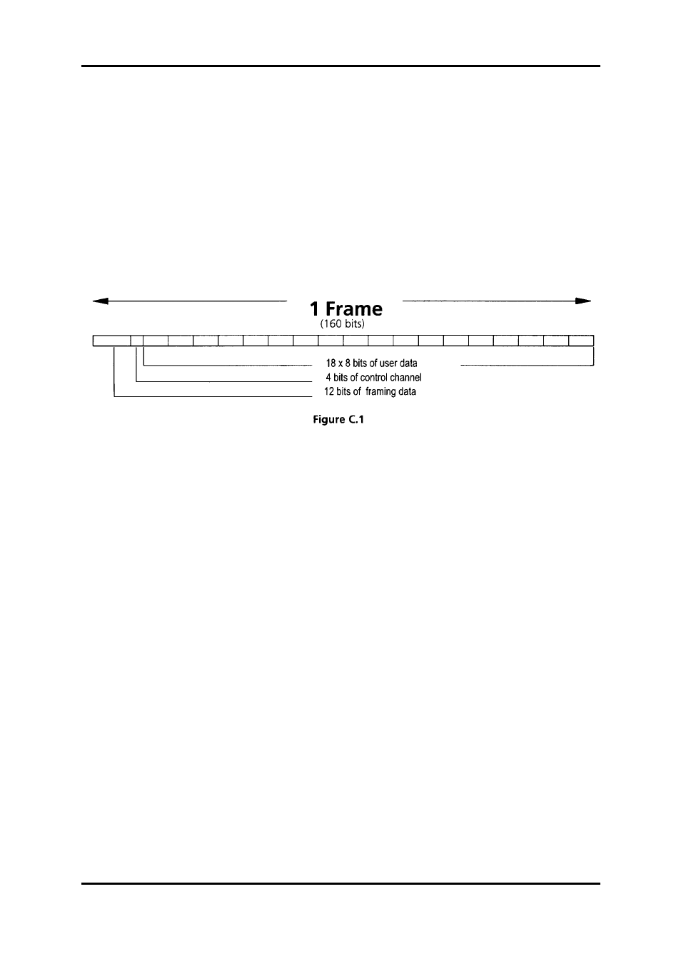
C.1 Frame Structure
For both rates the frame structure is the same. Figure C.1 shows the basic frame structure. Each frame
consists of 160 bits of which 12 are allocated to the framing pattern and 4 to the control channel. (These
4 bits per frame are termed the Comms channel). This leaves 144 bits, or 18 octets for user data. With
most rates the user data actually occupies 6 bits out of every octet, as one bit is used as the user status
line, and the other bit is used as an envelope alignment bit, (this bit is used by the system for the
multiplexing of lower user rates into the 71.1 / 142.2 kbps over all bit rates). There are several user rates
which do not have an alignment bit; these are 16, 32, 56, 64 and 128 kbps, consequently these rates will
not be able to use the envelope alignment error monitoring schemes. At the high rate the maximum
throughput for the user is 64 kbps (no status, no alignment); at double rate it is 128 kbps.
C.2 In Service Test Facilities
The In Service Test has access to two basic sources of information:
(1)
The envelope alignment bits
(2)
The comms channel
The use of the envelope alignment bits is slightly more straight forward.
At either end of the link the BBM monitors these alignment bits against tables held in ROM. Any bits
received in error are counted and can be displayed. For each frame there are 18 envelope alignment bits
for 18 x 6 bits of data. The effective data error rate can then be found from:
Envelope Error Count x6
Bit Error Rate (BER) = _______________________
User Data Rate x Time