Hardware setup, 36 asus cuv4x-dls user’s manual, Connectors 3. h/w setup – Asus CUV4X-DLS User Manual
Page 36
36
ASUS CUV4X-DLS User’s Manual
3. HARDWARE SETUP
Connectors
3. H/W SETUP
®
CUV4X-DLS
CUV4X-DLS
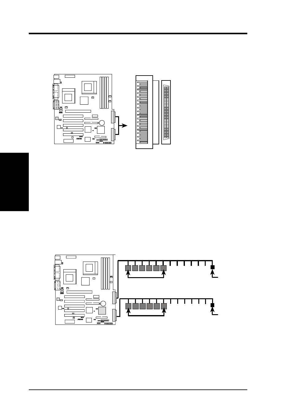
SCSI Connection Example
68-pin Internal SCSI Cable (Twisted-Pair Ribbon)
68-pin Female
Terminator
Internal SCSI Devices (up to 15 devices)
Channel A
68-pin Internal SCSI Cable (Twisted-Pair Ribbon)
68-pin Female
Terminator
Internal SCSI Devices (up to 15 devices)
Channel B
CUV4X-DLS
Onboard SCSI Connectors
®
CUV4X-DLS
35
68
34
1
SCSI-A
SCSI-B
68-Pin Ultra160/
Ultra2-Wide SCSI Connector
4) Two 68-pin Ultra160/Ultra3 SCSI Connectors
This motherboard has two 68-Pin Ultra160/Ultra3 SCSI connectors, one for each
of the two channels. Each channel can support a maximum of 15 devices as
specified by Ultra160/Ultra3 standards.
SCSI Connection Notes
The onboard SCSI chipset incorporates an advanced multimode I/O cell that supports
both single-ended (SE), Ultra3, and Ultra160 devices. With Ultra160/Ultra3 devices,
the SCSI bus platform performs at full Ultra160/Ultra3 speeds (up to 160MB/sec)
and extended cabling 12m (or 25m in a point-to-point configuration). When an SE
device is attached, the bus defaults to an SE speed and 1.5m cable length.
IMPORTANT: Connect SCSI devices as shown. Each channel should have only
one type of SCSI standard (e.g. Ultra160, Ultra3, Ultra-Wide). Mixing SCSI devices
on the same channel decreases performance of the slower device.
NOTE: Ultra160/Ultra3 SCSI devices do not have termination jumpers and must
use a separate terminator on the last connector (internal) or device (external).