UEi Test Instruments UTL260 User Manual
Page 4
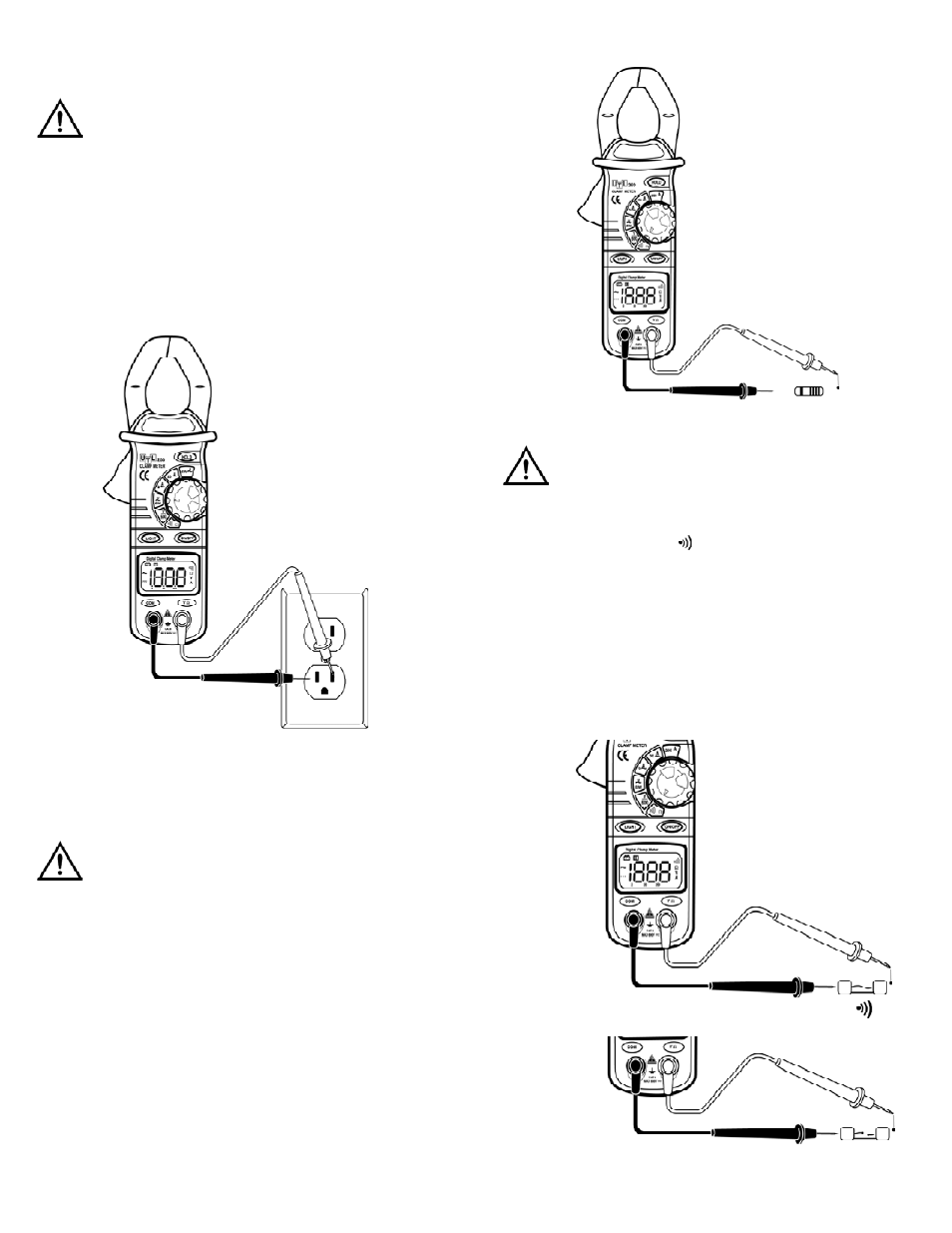
Continuity Measurement
WARNING!
Before taking any in-circuit resistance measurements, remove power
from the circuit being tested and discharge all capacitors.
1. Set the rotary switch to “ Ω“ range.
2. Connect the black and red test leads to the “COM” and “VΩ”
terminals respectively.
3. Connect the test leads to the resistance in the circuit being
measured (Fig 5).
4. When the test lead to the circuit is below 50Ω, it will be indicated
by a continuous beeping.
NOTE: Continuity test is available to check open/short of the circuit.
AC Voltage Measurement
WARNING!
Maximum input voltage of AC V range is 600Vrms. Do not attempt to
take any voltage measurement that exceeds 600Vrms to avoid electrical
shock hazard and/or damage to the instrument.
1. Set the rotary switch to the 600V~range.
2. Connect the black and red test leads to the “COM” and “VΩ”
terminals respectively.
3. Connect the test leads to the circuit being measured and read
the displayed value (Fig 3).
Resistance Measurement
WARNING!
Before taking any in-circuit resistance measurements, remove power
from the circuit being tested and discharge all capacitors.
1. Set the rotary switch to the 600V~range.
2. Connect the black and red test leads to the “COM” and “VΩ”
terminals respectively.
3. Connect the test leads to the circuit being measured and read
the displayed value (Fig 4).
UTL260-MAN
P. 3
(Fig 3)
(Fig 4)
(Fig 4)
Beeper
Short Circuit
Open Circuit