UEi Test Instruments DMEG3 User Manual
Page 7
Preparig Equipment Under Test
Isolation is a key factor in properly testing any insulation resistance
value. Whether you are testing a motor winding, transformer winding or
a cable, you must ensure that the component you are evaluating has no
path to ground or other circuits. Contactors and switches must be open
and terminal connections must be removed prior to testing.
Your insulation resistance tester is designed to place the DC charge on
the “LINE” terminal while the “EARTH” terminal often shares the
grounded contact with all other components.
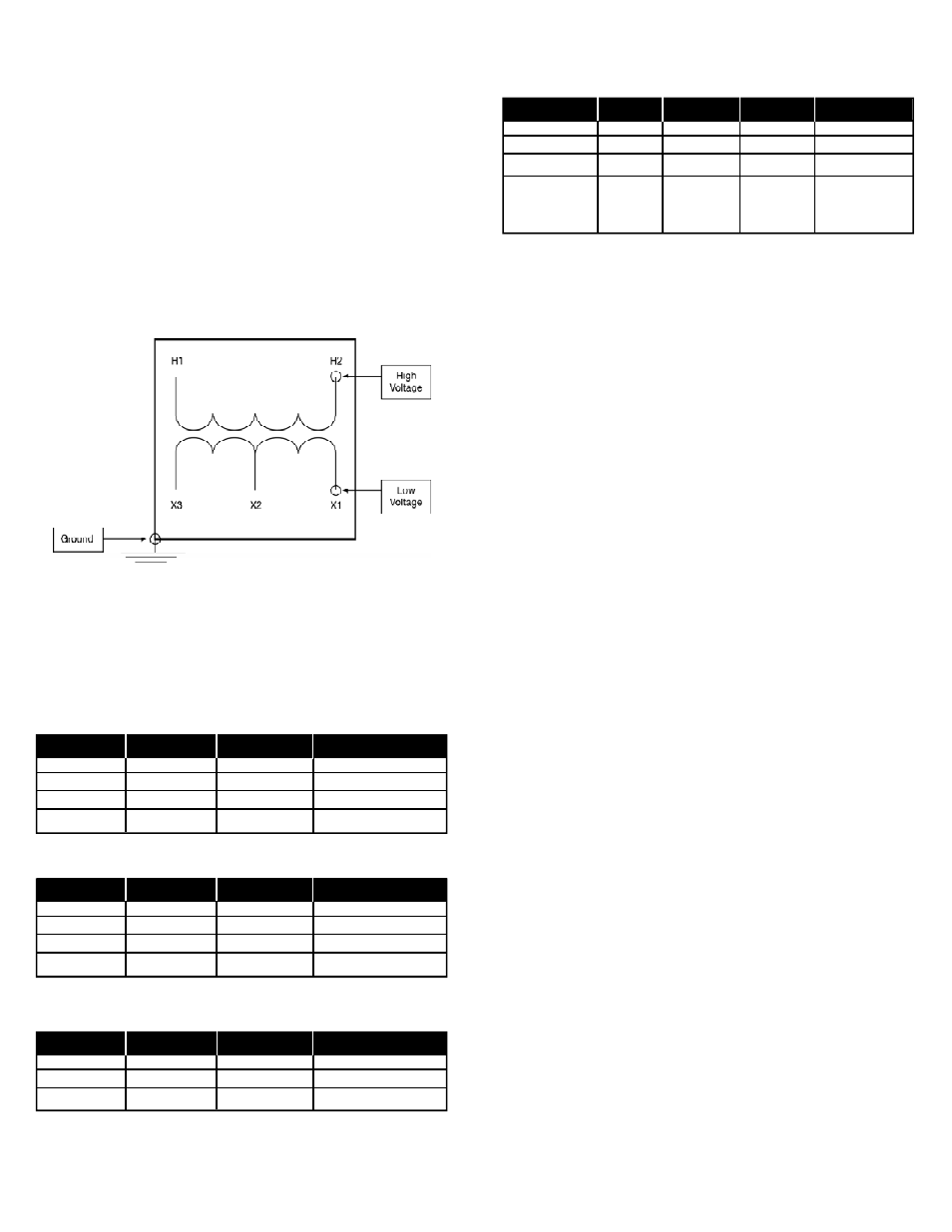
You can only test one cable, winding or component at a time, but they
ALL need to be tested independently (Fig 4).
When more than one connection is called for, connect the test
points together.
E = Earth L = Line
Single Phase Transformer Connection Sequence Table
Motor Connection Sequence Table
Insulated 3-Conductor Cable Connection Sequence Table
Shielded 3-Conductor Cable Connection Sequence Table
60-Second (spot reading) Method
Spot readings are often used as predictive/preventive maintenance
tools. Readings are generally taken at regular intervals (quarterly,
semi-annually, etc.) and recorded on a chart that stays with the
equipment being tested. To make an analysis of a motor using
this method:
1. Check and record equipment temperature.
2. Check dew point temperature of the ambient air-equipment
under test must be above dew point temperature for
accurate results.
3. Ensure no power is applied to the equipment under test and all
connections are removed in order to totally isolate the motor,
cables or equipment from other circuits. Use the connection
tables to determine where to make connections.
•
If you are testing a motor, the brushes must be removed
prior to testing
•
Connect all components that are NOT being tested, including
motor housing, to ground (EARTH)
•
Test Field and Stator windings independently
4. Turn your instrument power on (DMEG3).
5. Place rotary function select switch to the INSULATION position,
with the correct voltage selected - Use the same voltage
every time.
6. Make connections according to the sequence tables provided or
as your circumstances require.
7. Using a stopwatch or watch with a second hand, begin a
60-second test at the same time you press and hold (or lock)
the “Press to Test” button.
8. At the end of 60-seconds, read and record the insulation
resistance value.
9. Apply temperature correction factor and record results on
PM Chart (Fig 4).
DMEG3/IRT3-MAN
P. 6
(Fig 4)
Sequence
X1
H2
Ground
1
E
L
E
2
L
E
E
3
L
E
4
E
L
Sequence
L1
L2
L3
Shield
1
E
L
E
E
2
L
E
E
E
3
E
E
L
E
4
(Remove Shield
E
E
E
L
from Ground)
Sequence
Stator
Field
Ground
1
E
L
E
2
L
E
E
3
L
E
4
E
L
Sequence
L1
L2
L3
1
E
L
E
2
L
E
E
3
E
E
L