UEi Test Instruments DL235 User Manual
Page 3
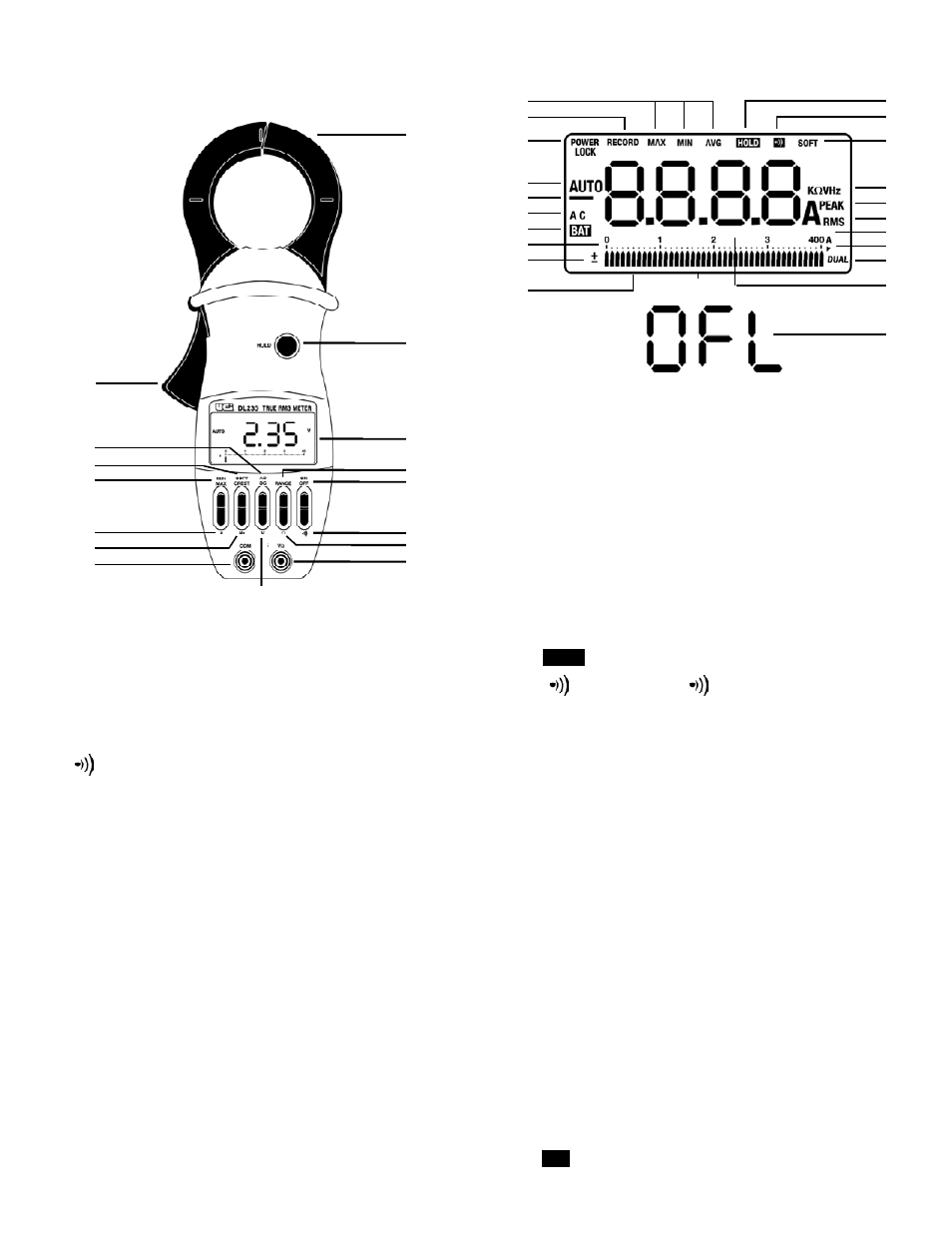
LCD Display Functional Description
14. Soft Cre s t : Select “SOFT” for a running 3-second average, or
CREST half cycle peak amperes.
15. AC/DC: Selects AC or DC mode.
16. Lever: Opens and closes clamp jaws.
17. Record: Displayed (blinking) when “MIN/M AX / AV G“ values are
being recorded. Duration of RE CO RD is limited by battery life.
18. MIN/MAX/AVG: Displayed in “REC ORD” mode by pressing
“MIN/M AX” push-button.
19.
: Displayed when “HOL D” push-button has been pressed.
20.
: Displayed when “ “ push-button has been pressed.
21. Soft: Displayed when current flow readings or Hz or V readings are
softened out over 3-second interv a l s .
22. KΩVHz: Displayed when measuring ohms or voltage or frequency.
23. Peak: Displayed when current flow readings are in half-cycle
peak amperes (CRES T m o d e ) .
24. RMS: Displayed when current reading is in amperes rms.
25. Off-Scale Arrow: Displayed when bar graph pointer is off sca l e .
26. Dual: Displayed when measuring frequency in digital and
amperes in bar graph simultaneously.
27. A: Displayed when meter is measuring amperes.
28. Digital Display: Displays 3999 counts, with two decimal points
relative to the two ranges. But, displays 9999 counts in frequency
mode. Display in updated 4 times each second.
29. Pointers: Displayed to indicate position on bar graph scale.
Positions are updated 20 times each second.
30. Analog Display Polarity: Displays + or - when the pointers
are displayed.
31. 0 to 400A: (or 0 to 800A) numeric reference for the bar gra p h .
32.
: Displayed when internal battery needs replacing.
C o n t rols and Indicators
1. C l a m p : Opens 2.04 inches (52 mm) to enclose conductors.
2. Hold: Freezes reading in digital display.
3. Display: Liquid crystal display.
4. Range: Selects 0 to 40A, 0 to 400A, or AUTO .
5. On Off: Selects meters power ON or power OFF.
6.
: Selects continuity testing mode.
7. Ω: Selects ohms measurement mode.
8. VΩ: Volt, ohms, continuity test input terminal.
9. V: Selects volts measurement mode.
10. COM: Common terminal.
11. Hz: Selects frequency measurement mode.
12. A: Selects aperes measurement mode.
13. MIN/MAX: Selects “REC ORD” mode and displays
recorded MIN / M AX / AV G .
DL235-MAN
P. 2
1
18
BAT
HOLD
2
3
4
5
6
7
8
9
10
11
12
13
14
15
16
17
36
35
34
33
32
31
30
29
37
19
20
21
22
23
24
25
26
27
28
29