Sterlco SDD Series User Manual
Page 67
67 of 96
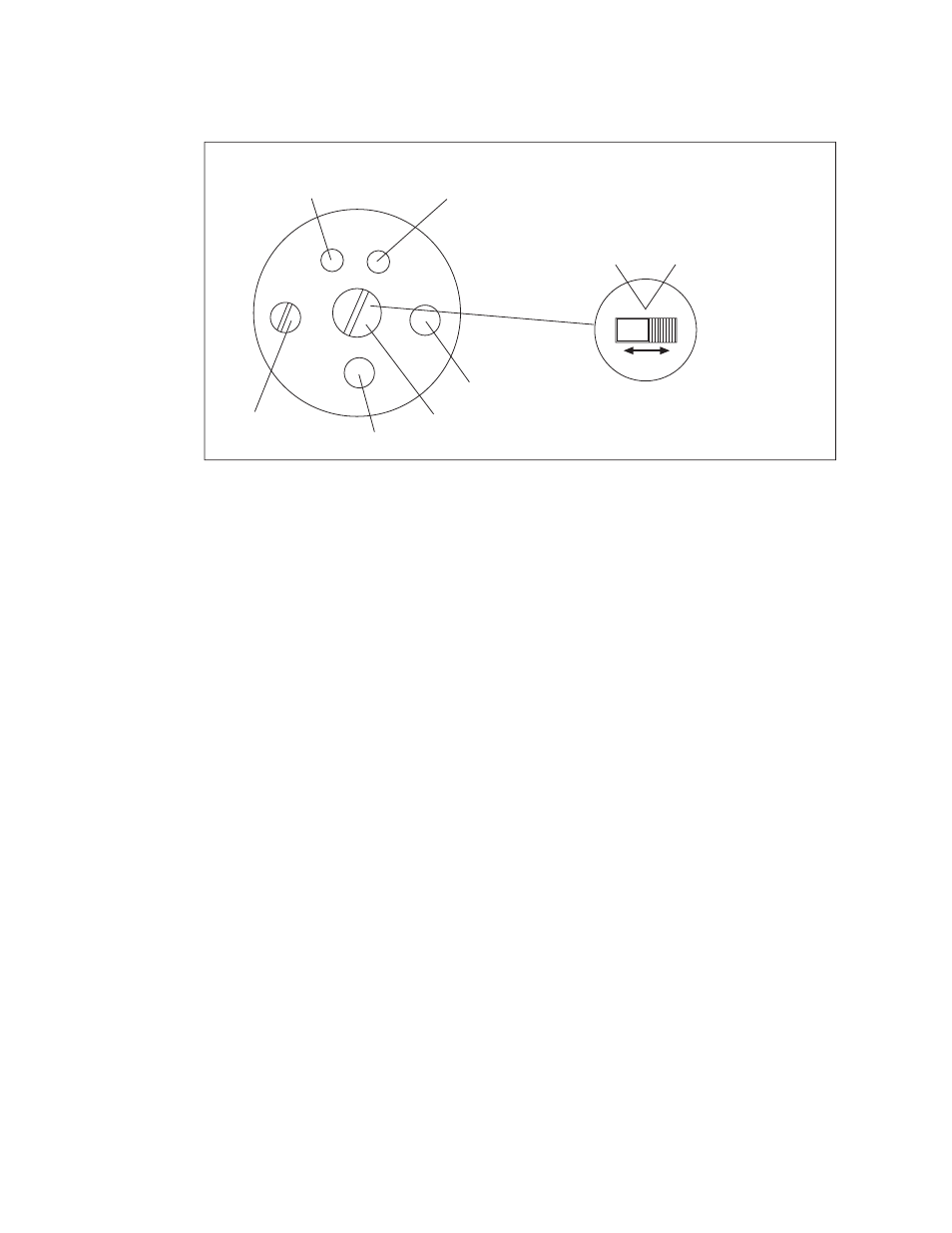
LED Yellow (Station)
on: Station Filled
off: Station Emptied
LED Green (Level Probe)
on: Power Supply Available
off: Power Supply Not Available
Trim-pot with
Plastic Screw M3
Cable
Blind Lid
Protective Screw
npn: Normally Closed
pnp: Normally Open
1
0
npn: Normally Open
pnp: Normally Closed
Level Probe
Figure 7. Level Sensor Adjustment Screw
4. Turn the trim-pot until the yellow control lamp just switches off.
NOTE: Turning the trim-pot to the left decreases the switching sensitivity, and
turning it to the right increases the sensitivity.
5. Fill the dosing station until the level probe is two-thirds covered. The yellow control
lamp should now switch on again. If not, repeat Step 4.
6. Reinstall the plastic screw (M3).
NOTE: The sliding switch under the cover must be set on “0”.
Communication Protocol Interfaces
The Digital Dosing feeder can be controlled remotely through ODBUS RTU protocol. Contact the
Sales Department at 810.720.7300 for more information.
OPTIONAL Additive Hoppers
Various styles of additive hoppers and options are also available for the Digital Dosing feeder.
Contact the Sales Department at 810.720.7300 for more information.