Anaheim MDM60001 User Manual
Page 4
5
6
PIN DESCRIPTIONS P2
Pin#
Description
1
Reduce Current: Phase Current Reduction Input. A resistor
between this pin and pin 2 (Connector P2, Current Adjust) will
proportionately reduced the current in both windings (1 second after
the last positive going edge of the step clock input). The amount of
current reduction will depend on the value of the resistor used.
2
Current Adjust: Phase Current Adjustment input. A resistor
connected between this input and the ground input (connector P2,
Pin 3) is used to adjust the maximum Phase Current in the motor. A
resistor MUST be connected to this input.
3
0VDC: Supply Voltage Ground. ( Return )
4
+V: Supply Voltage Input. (+24 -75VDC)
5
Phase 4: of the Step Motor
6
Phase 2: of the Step Motor
7
Phase 3: of the Step Motor
8
Phase 1: of the Step Motor
Table 2 - CONNECTOR P2
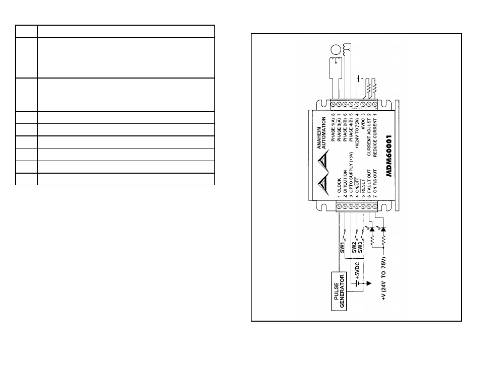
TYPICAL HOOK-UPS FOR APPLICATION:
FIGURE 1