Ar ch ive d – Seametrics EX80 Series v.2 User Manual
Page 11
oPEration & maintEnancE
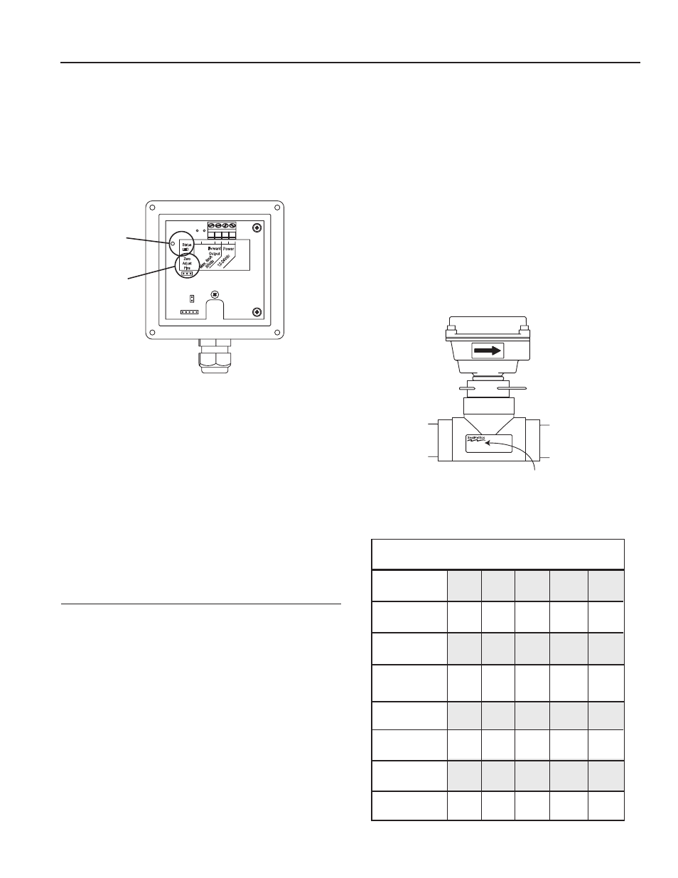
Zero adjustment. When the EX81 or 82 is powered up
and there is no flow, there should be no output pulses (or,
if connected to the FT420, flow rate should read “0”). If
there are pulses it may be necessary to adjust the flow
meter under no-flow conditions after it has been installed.
This should only be done if the indicated flow is low, near
the lower cutoff.
To perform the adjustment, after determining that there is
a full pipe with no flow, short between the two pins marked
“Zero Adjust”. A red LED light will come on for approxi-
mately 50 seconds and then go out. The zero adjustment
is completed.
minimum Flow.
As with any other flow sensor, there is a rate
below which the EX80-series sensor cannot read. Check the
flow rate table below for the minimum flow rate detectable
by the sensor for a given pipe size.
Presence of Flow indication.
To assist in troubleshooting,
the “Status LED” has two blinking modes in normal
operation. When there is no flow detectable by the meter
(below minimum threshold) the LED blinks ever y 8.0
seconds. When there is detectable flow, the same indicator
blinks every 3.0 seconds.
Filtering.
The software of the EX80-series sensor filters
out electrical noise and averages sudden variations in the
flow to smooth the output. It takes a matter of seconds for
the flow sensor to get up to full output when it is powered
up or when flow begins.
calibration (“K-factor”). The K-factor represents the actual
number of pulses per gallon the meter produces during a
flow test. This number can be entered into your electronic
control to make it read properly. If the EX80 Series meter
is ordered with a tee fitting, it is factory-calibrated in the
fitting and the K-factor is indicated on the side of the fitting
(see diagram).
Find your K-Factor Here
Page 9
1” 1-1/2” 2” 3” 4” 6” 8” 10”
• Min .50 1.1 2 4.5 8 18 31 49
•
Max 50 110 196 440 783 1763 3133 4895
FloW ratE (gPm)
30
Vdc
Max. 6m
A
- +
- +
12-24
Vd
c
3
4
5
6
2
1
Power
Forward
Output
Status
LED
Zero
Adjust
Pins
Zero
adjust
Pins
Electrode coating.
Grease or other adhering, non-
conductive materials can stop flow detection if the
electrodes become heavily coated. To clean the electrodes,
remove the sensor from the pipe and gently scrub the
electrodes (three silver bumps) on the reading face of the
flow sensor. A mild soap (dishwashing liquid for example)
can be used to aid the cleaning process.
10031295
EF81T-P200
K:158.42
If the EX80 Series meter is ordered with a saddle or wel-
dolet fitting, find your K-factor in the chart below.
3” 4” 6” 8”
10”
K-FactorS SaDDlES & WElDolEtS
70.397
78.748
62.385
70.397
76.371
78.371
70.672
57.376
40.985
45.360
36.626
40.985
43.552
44.638
41.517
37.320
6.674
7.322
6.173
6.674
7.230
7.500
6.674
6.197
10.497
11.495
9.642
10.497
11.201
11.622
10.445
9.503
18.130
20.084
16.510
18.130
19.513
20.223
17.778
16.915
Status
lED
PVc/Steel
Sch. 40
PVc/Steel
Sch. 80
Stainless
Steel (10S)
Stainless
Steel (40S)
copper tubing
(type l)
copper tubing
(type K)
brass Pipe
Duct. iron
(class 52)
AR
CH
IVE
D
(Includes Dates 6/28/05 to 10/06)