Dis con tin ued – Seametrics FS20 User Manual
Page 2
Setting
See example diagram for method of setting. Note that
Low Flow energizes the relay when flow
drops below
the set point, and High Flow energizes when it
rises
above the set point.
Connect Power. If using the power cord provided,
wait to plug it in until after the front panel has been
replaced. Terminal connection is only necessary for
conduit installations. Remove the power cord provided
and connect power, following the Connections diagram.
Do not energize the circuit until the front panel has been
replaced.
Replace Front Panel. Reverse the removal proce-
dure.
Determine Trip Points. Trip point frequencies are in
pulses per minute. To calculate, multiply the pulses
per gallon provided by the meter (“K-factor”) by the
gallons per minute at which the alarm output is desired.
OFF
ON
16384
32768
8192
4096
2048
1024
512
256
32
64
128
16
8
4
2
1
Setting equals
the sum of
the switches
turned "ON".
L
O
W
F
L
O
W
Example
1000 Pulses
per minute
Example: The meter produces 50 pulses per
gallon. Low-flow relay output is desired at
20 gallons per minute.
50 pulses/gallon X 20 gallons per
minute = 1,000 pulses/minute
Set Low Flow to 1,000.
Set Trip Points. The DIP switches under the front
clear cover are used to set trip point frequencies.
20419 80th Ave. So., Kent WA. 98032 USA
Phone: 253-872-0284 Fax: 253-872-0285
www.seametrics.com 1-800-975-8153
2 of 2
GND
SIGNAL
EXTERNALLY-PACED
METERING PUMP
DRY CONTACT
TYPE METER (MR,WPR)
GND
GND
SIGNAL
SIGNAL
+12 VDC
+12 VDC
PUMP+
SOLID STATE TYPE
METER (ME,IP,WT)
SOLID STATE TYPE
METER (ME,IP,WT)
Hot
Neutral
Ground
High Flow Relay
NO NC N G
NO NC N G
Normally Open
Normally Closed
Common
Unused
Unused
Common
Normally Closed
Normally Open
110 VAC Input
Low Flow Relay
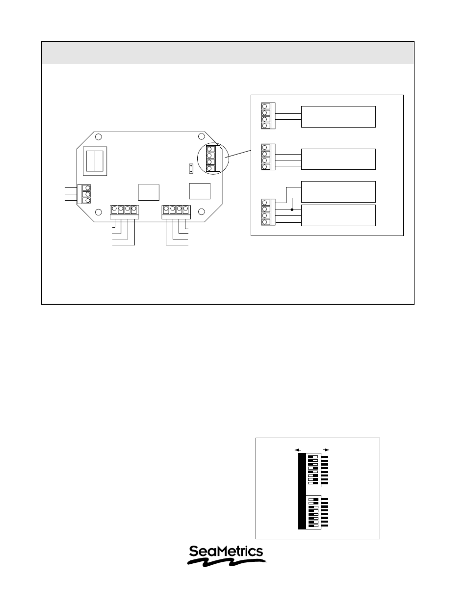
FS20 Connections Diagram
DIS
CON
TIN
UED