Ar ch ive d – Seametrics AG2000 v.2 User Manual
Page 2
AG2000 Cable
(-)
(+)
AG2000
Pair 1-Black
Pair 1-Red
Pair 3-Black
Pair 3-Red
Shielded Burial Cable
3 Twisted Pairs
22 AWG Stranded
Pair 2-Black
Pair 2-Red
Blue
Orange
White
Colored Sleeves*
*Colored Sleeves readily identify the 3 pairs.
If the cable needs to be cut back, the pair
identification is printed on each wire.
Power Supply
7-24 Vdc
75 mA min
Drain Wire
Pair 1: Serial Output (Technician Use Only)
Pair 2: Pulse Output, 30 Vdc max, 10 mA max
Pair 3: External Power, 7-24 Vdc, 75 mA min
Drain: Connect to earth ground
EXTERNAL POWER
Page 2
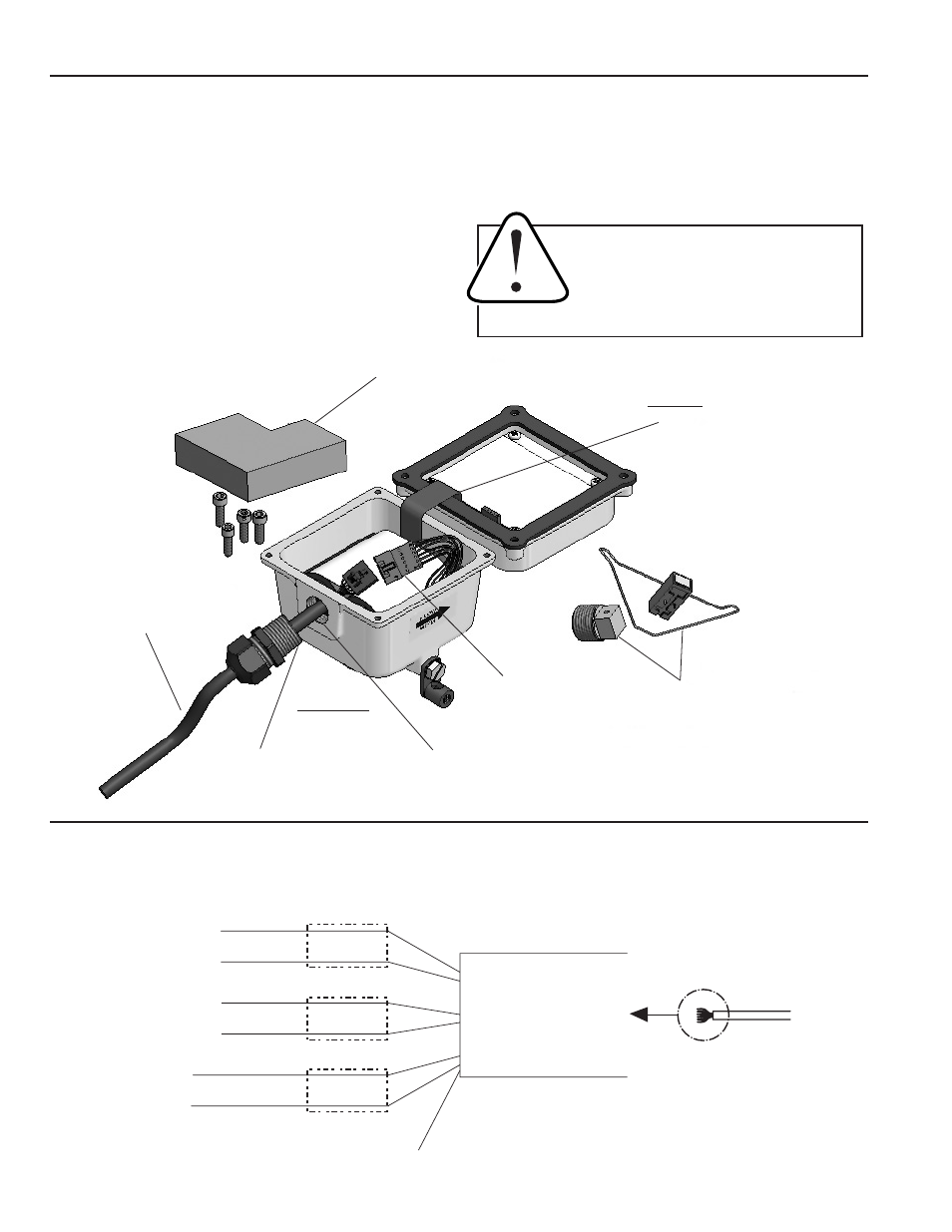
Use the diagram below as a guideline for installing the DC30/DC35 optional input/output cable to the AG2000 meter.
(NOTE: If you ordered the input/output cable factory-installed, you may disregard this step.)
Then proceed to the appropriate wiring diagram for your application on subsequent pages.
INSTALLING THE DC30/DC35 OPTIONAL CABLE
CAUTION:
When the AG2000 is used for
regulatory purposes, ensure that regulatory
requirements are met before breaking the
security wire-and-seal. Replace wire-and-seal
according to regulatory requirements when
finished installing the DC30/DC35.
Apply Loctite Pipe Sealant
#567PST to outer half of
threads, wiping in a full
circular pattern.
Apply Loctite Pipe Sealant
#567PST to end 1/3 to 1/2
of threads, wiping in a full
circular pattern.
Partial View
(Meter Body Not Shown)
Control Connector
Discarded Parts
CAUTION:
Do Not Stress Cable
IMPORTANT:
Be sure to apply
sealant to threads
Set aside the foam battery
restraint & cover screws
DC30/DC35
Optional Input/Output Cable
AR
CH
IVE
D
(Includes Dates 7/19/06 to 1
1/06)