Seametrics PD10 User Manual
Page 4
0 1 2
3
45
67
8
9
0 1 2
3
45
67
8
9
0 1 2
3
45
67
8
9
0 1 2
3
45
67
8
9
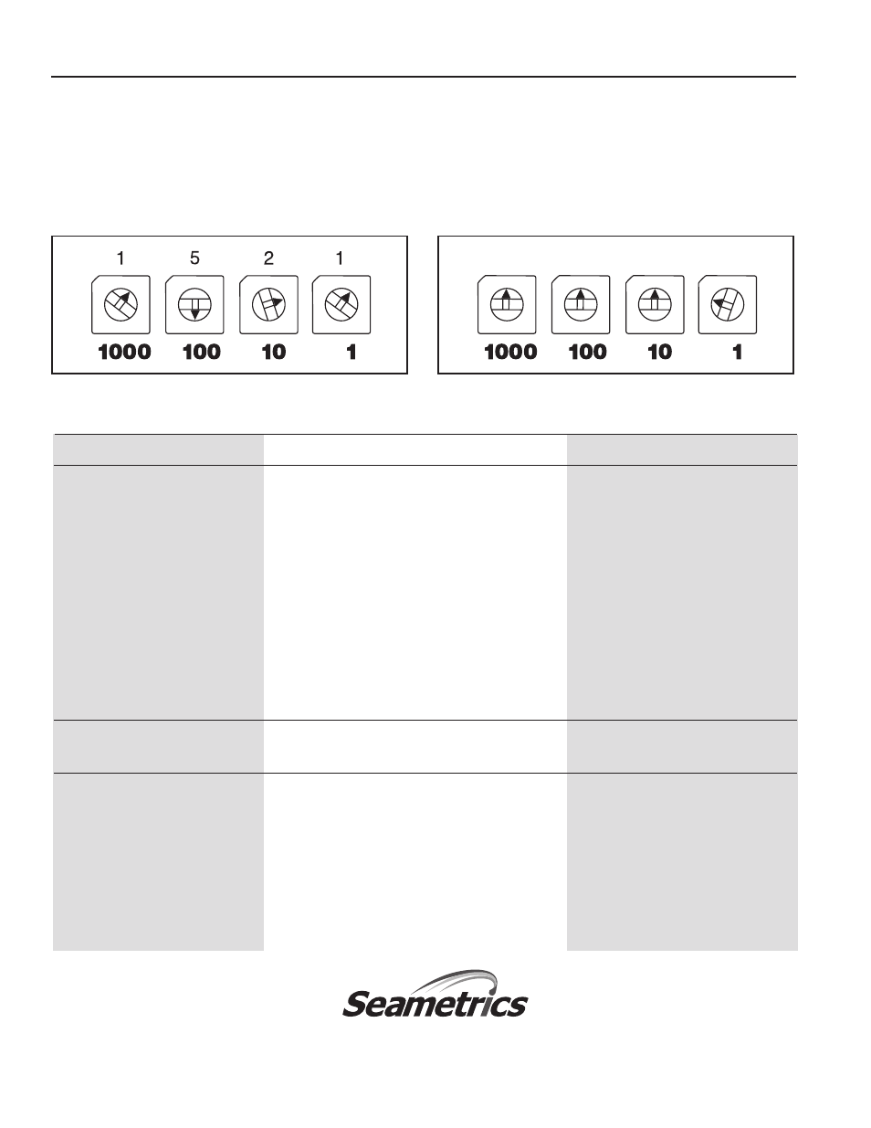
Setting Examples
The four numbered rotary switches marked "1000", "100",
"10", and "1" control the ratio of meter pulses to pump
strokes. Before setting the switches, disconnect power
to the unit by removing the connector from the pump or
unplugging the power adapter.
Problem
Probable Cause
TROUBLESHOOTING
Try...
SETTING
Metering pump not stroking
Meter dials not turning
Check visually, then check for
adequate flow
Meter pickup not working
Remove from meter, check with a
magnet
Pump connector not plugged in all the way
Check or tighten threaded locking
ring (LMI)
Pump doesn’t supply power to the PD10
Check pump manual, add power
supply
PD10 set to large number or all zeroes
Check rotary switches, esp. for
leading zeroes
Pump strokes continually
Pump not set for external pacing
Check pump manual and selector
switch
Pump doesn’t stroke often enough
PD10 set for wrong number
Review setting on this page, check
or too often
rotary switches
Multiple contacts from meter
Set PD10 to 1 contact/pump stroke
(0001) and see if the pump strokes
once for each magnet revolution
Meter ordered with wrong pulse rate
Check meter model/serial tag
0 1 2
3
45
67
8
9
0 1 2
3
45
67
8
9
0 1 2
3
45
67
8
9
0 1 2
3
45
67
8
9
8
(Set Leading Switches To Zero)
To set any four-digit number, rotate the dials to the appropri-
ate numbers. For example, to set 1521, set the four switches
to "1", "5", "2", and "1". Any unused switches should be set to
zero. For example, to set 8, position the dials to "0", "0", "0",
"8". See samples below.
LT-65200031-081314
8/13/2014
Seametrics Incorporated • 19026 72nd Avenue South • Kent, Washington 98032 • USA
(P) 253.872.0284 • (F) 253.872.0285 • 1.800.975.8153 • www.seametrics.com
Page 4