Ps40 pulse splitter, Connections – Seametrics PS40 User Manual
Page 2
PS40
Pulse Splitter
Seametrics Incorporated • 19026 72nd Avenue South • Kent, Washington 98032 • USA
(P) 253.872.0284 • (F) 253.872.0285 • 1.800.975.8153 • www.seametrics.com
LT-65650018-042512
4/25/12
BL
AC
K
RE
D
BL
AC
K
BL
AC
K
RE
D
RE
D
BL
AC
K
RE
D
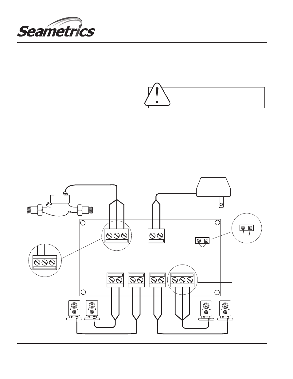
JP1
JP1
Clip this jumper for
high speed operation
MJR METER-
TWO-WIRE
CONNECTION
NC
CO
M
NO
+O
P
-O
P
+O
P
-O
P
+O
P
-O
P
Do not use for high
speed operation
10-32 Vdc
power supply
+Vdc
-Vdc
+12V
SI
G
GN
D
+12V
SI
G
GN
D
MJE METER
Connections.
Remove the PS40 cover to access the terminals.
Follow the Connections diagram. Use the included nuts to
secure the strain reliefs on the inside of the enclosure before
connecting to the terminals.
Power.
A DC power supply of 10 to 32 Vdc is required. Connect
the +V and -V terminals to the DC + and - as shown.
Sensor.
If using a two-wire (e.g., MJR meter), note which two of
the three terminals are to be used. Either of the sensor wires
can be connected to either of these two terminals. Three-wire
sensors (e.g., MJE meters) are polarity-sensitive and must be
connected to the appropriate terminals by standard Seametrics
color code: red is +, black is - , and white is Signal.
Output.
Three of the outputs are transistor, the fourth is relay.
The transistor outputs will operate almost all pulse-responsive
metering pumps and all Seametrics controls, provided that the
polarity is correct. The relay output is identified by its terminals
marked NO (normally open), COM (common), and NC (normally
closed). The relay output will operate essentially everything,
including the very rare pump or control that will only work with
dry contact.
High Speed Input.
It may be occasionally desirable to use the
PS40 with a high-speed input, such as an IP80 paddlewheel
flow sensor. If the sensor will be putting out more than 50
pulses per second, it is necessary to disable the relay output,
which cannot operate at such high speeds. To do this, clip the
jumper marked JP1 (see diagram). Note that the relay output
terminals cannot be used in this case.
CONNECTIONS
Caution:
The relay output is designed for
electronic controls only. Maximum current
load is 250 mA.