Seametrics WMP-Series User Manual
Page 6
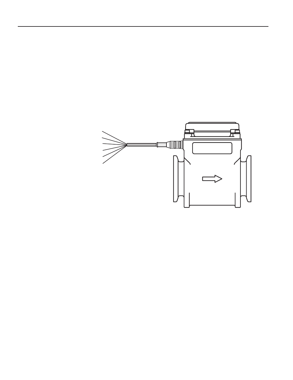
ELECTRICAL CONNECTIONS, CABLE CONNECTIONS and OPERATION
Black: Pin 4 = (–) Power
Blue: Pin 3 = (+) Pulse
White: Pin 2 = (–) Pulse
Brown: Pin 1 = (+) Power
Gray: Pin 5 = Ground
Shield Drain Wire
CABLE CONNECTIONS
ELECTRICAL CONNECTIONS
WMP104.
The WMP104 is battery-powered totally self-con-
tained and does not require any electrical connections (there
is no output on the WMP104 model).
WMP101.
A connector is provided on the outside of the
WMP101. To connect to the meter, plug the cable in and
hand tighten the retaining threads. Follow the diagram to
make connections. If you are using the pulse output, connect
power first and determine that the meter is working properly
by observing the display. Then connect the pulse output.
OPERATION
Grounding (WMP101).
For best performance, especially in
chemically noisy environments, the gray ground wire and the
bare drain wire should be connected together and to a good
earth ground as close to the meter as possible. Metal pipe
and fittings in contact with the fluid should also be bonded to
the same earth ground with corrosion-resistant connections.
Display.
The display reads flow rate and accumulated total,
in the units for which it was ordered. The top line is total, the
bottom line is rate, and indicators give the units (ac-ft, GPM
for instance.) Empty or partially-full pipe is automatically de-
tected and is indicated by a reading of “ – EP – “.
Battery.
The standard batteries are user replaceable with an
approximate 1-2 year life depending on usage. An extended
battery life option offers an estimated 2-4 year life depending
on usage. On the battery-powered WMP104 there is a low-
battery indicator (“low bat”) when the battery voltage drops
below a certain point. Batteries should be changed within
four weeks of the appearance of this indicator.
5