Seametrics AG2000-Series User Manual
Page 2
Page 2
INSTALLATION
Tamper-Evident Seal.
The battery-powered AG2000 has a seal
wire to protect against unauthorized access. The seal can be
broken to change units of measure, replace the battery pack, or
to field-install a power/output cable (see page 4). CAUTION: If
water usage regulation is in effect, only a person authorized by
your regulatory agency should break the seal wire, and replace
it when finished.
Positioning the Meter.
These meters can be installed horizontally,
vertically, and in any radial position. If sludge accumulation
is possible, vertical or horizontal placement with the register
at a 45˚ angle is recommended. Using a check valve on the
upstream side of the meter, and/or an air vent (vacuum relief
valve) in the same, unobstructed run of pipe as the meter, is
required in any installation where the meter may be exposed
to suction when the system is not in normal operation. Suction
can cause damage to the liner. Liner damage caused by
suction, without the use of a check valve and/or air vent, may
void the warranty.
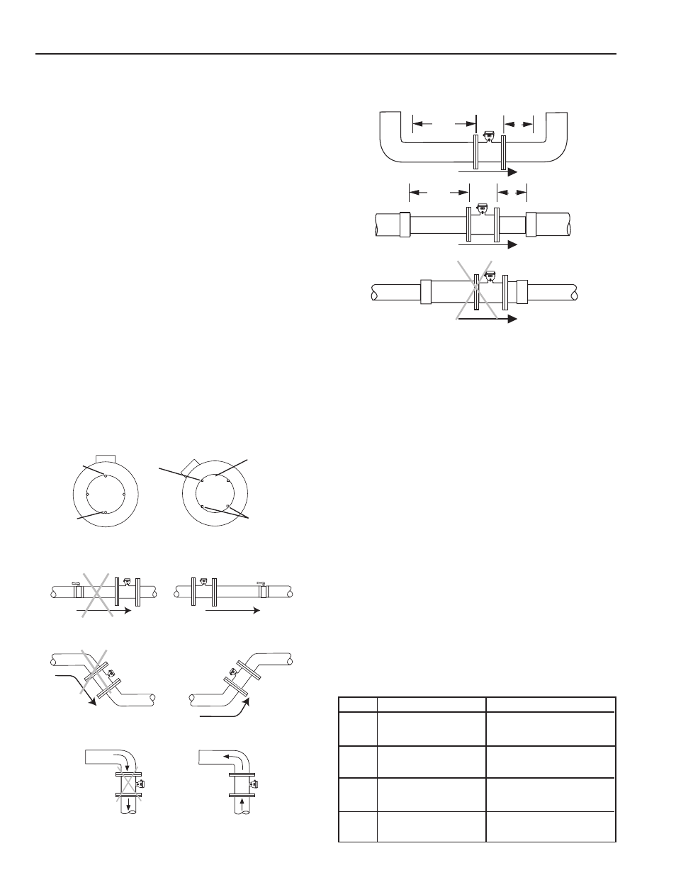
Full Pipe Recommendations
. All magmeters require a method
for determining that the pipe is empty, to prevent false reading.
This meter is designed to go to zero reading if one or more
electrodes is exposed. For highest accuracy, install the meter so
that the pipe will be full when there is flow. If air bubbles may be
present in the pipe, rotate the meter by one flange hole to position
the control housing at a 45˚ angle. See mounting diagrams below.
Straight Pipe Recommendations
. See the diagrams below
for manufacturers’ recommendations. Local regulations may
vary, confirm before installing to assure compliance.
2X
1X
2X
1X
pipe size
pipe size
pipe size
pipe size
Elbows
Reduced Pipe
(not recommended)
Expanded Pipe
FLOW RANGE
Fittings and Flanges
. The AG2000 flanges have standard ANSI
150 lb. drilling, and should match up with any other ANSI 150 lb.
flange. IMPORTANT: Piping protruding beyond welded-on flange
faces may damage meter sealing surfaces.
Temperature
. These flow sensors are recommended for operating
temperatures of 10˚ to 130˚ F (-12˚ to 54˚ C) and non-operating
temperatures of -40˚ to 158˚ F (-40˚ to 70˚ C).
Calibration
. The AG2000 is factory calibrated and cannot be
recalibrated in the field.
Protecting the Meter.
A weather guard is recommended
(Seametrics part #31388) for environmental protection.
Conductivity.
The AG2000 requires media with >20 microSiemens/
cm of conductivity.
Chemigation Applications.
Magmeters in chemigation ap-
plications must be placed either upstream of the chemical
injection line, or far enough downstream for complete mix-
ing to occur before the solution reaches the meter. Proper
placement prevents spikes and drops in readings that result
when fluids of different conductivity pass through the meter.
(For more information, refer to the technical bulletin on the
Seametrics website Downloads page.)
Minimum Maximum
4”
12 gal/min
1,000 gal/min
(.75 liter/sec)
(63 liter/sec)
6”
32 gal/min
2,400 gal/min
(2 liter/sec)
(151 liter/sec)
8”
60 gal/min
4,400 gal/min
(4 liter/sec)
(278 liter/sec)
10”
95 gal/min
7,000 gal/min
(6 liter/sec)
(442 liter/sec)
Possible Problem: Air pockets,
accuracy loss, empty pipe reading
Better Installation: Keeps pipe full
at sensor for accuracy
Possible Problem: Air can be
trapped, loss of accuracy
Better Installation: Allows air
to bleed off, higher accuracy
Not Recommended: Vertical
downflow, open discharge
Possible Problem:
Air bubbles and sediment on the
electrodes can affect accuracy.
Better Installation:
Improved accuracy results from
unimpeded electrodes.
Electrode
moved from
top by rotating
meter
Intermittent air
bubbles
miss electrode
Intermittent air
bubbles
pass over
electrode
Possible
sediment
build-up
Electrodes free
from sediment
build-up
Better Installation: Vertical
upflow with full pipe
Note: See Technical Bulletin ‘Piping Configurations for AG2000 Magme-
ters’ at www.seametrics.com for additional configuration information.