Wtp meter, Wtc and wts meters – Seametrics WT-Series Turbine User Manual
Page 3
Page 3
INSTALLATION
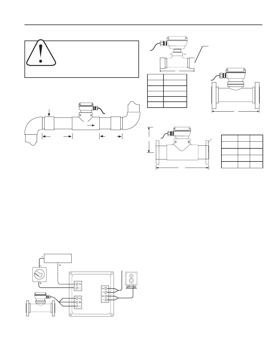
Piping Conditions.
Installing the meter with 10 diameters of
straight pipe upstream and 5 downstream is recommended.
CONNECTIONS
For operating instructions for the various electronic modules,
consult the manual for the specific module, included with the meter
at purchase.
INSTALLATION, CONNECTIONS, MAINTENANCE and REPAIR
CAUTION:
These water meters are not
recommended for installation downstream
of the boiler feedwater pump where instal-
lation fault may expose the meter to boiler
pressure and temperature. Maximum recom-
mended temperature is 120˚ (PVC) or 200˚ (Metal).
MAINTENANCE and REPAIR
Recalibration.
If it is necessary to recalibrate the meter for any
reason, this can be done by any Seametrics-authorized facility.
Call your supplier for information.
Turbine Insert Removal and Installation.
CAUTION: First
remove all pressure from the line. Then remove the screws or
bolts that hold the insert in place (or the U-clip in the 2” meters)
and tug gently until the insert comes free. A twisting motion
can help to loosen the O-ring seal. Reverse the procedure to
reinstall, after coating the O-ring with lubricant (plastic compat-
ible in the WTP). Do not overtighten.
Rotor and Shaft Replacement.
Examine the rotor to determine
if bearings or shaft are damaged or excessively worn. The rotor
should spin smoothly and freely, with no visible wobble. Back
and forth play should be very minor, less than 1/64”. If it is
necessary to replace the rotor or shafts, first back out both
shafts with a small blade screwdriver. The rotor will come free
as soon as the shaft ends come free of the rotor bearings. Re-
verse the procedure to reinstall. Note: Do not overtighten the
shaft screws. Check to be sure that a small amount of free play
between the shaft ends and the bearings remains.
Sensor Replacement.
This is rarely necessary. However, cer-
tain electrical conditions can damage the sensor. To replace
it, first remove the electronics module. Disconnect the sensor
leads from the electronics module terminals and remove the
threaded plug over the sensor. Finally, remove the sensor by
pulling on the sensor leads. A gentle tug should be sufficient.
Reverse the process to replace the sensor.
Loop Power Supply
24-36 Vdc (dep on device)
To Other
Control
4-20 mA De
vice
Red
White
Black
Powe
r
4-20 mA
Sensor
Puls
e
Output
Sensor Output
Black
Black
Red
Position.
The WT-Series are all-position meters, operable in
a vertical or horizontal position, with the meter insert in any
radial position. A horizontal position is preferred if there is a
risk of air becoming trapped due to constant low flows. Operat-
ing the meter in partially-filled pipe will result in inaccuracies.
Flanges.
For 3-8” WTC and WTS meters, standard flanges
are 150 lb. ANSI drilling. 2” WTC or WTS meters and all PVC
meters can be installed with optional flanges according to pipe
manufacturer’s recommendations. For PVC a bolt torque of
10-20 ft-lbs. for 2” flanges, 20-30 ft-lbs. for 3” and 4” flanges,
and 35-50 ft-lbs. for 6” flanges is recommended.
Either partial or full-face gaskets can be used. Tighten the
bolts evenly. Use care to prevent a misaligned gasket from
entering the flow stream.
10X Dia.
5X Dia.
Straight coupling can
be part of length
FLOW
WTP
A
Optional
Flanges
B
WTP Meter
Size A B
2” 10" 7.5"
3" 12" 6.5"
4" 14" 7.0"
6"
18" 8.5"
A
A
WTC and WTS Meters
3"- 8"
Size
Dim A
2"
* 8"/‡10"
3"
12"
4"
14"
6"
18"
8"
20"
*Without flange
‡With flange
2"
2” FEMALE NPT
(150 lb. Flange opt.)