Seametrics PE102 User Manual
Page 3
+
_
S
+
_
+
_
+
_
INSTALLATION and CONNECTIONS
INSTALLATION
Positioning.
The PE102 can be mounted vertically or horizon-
tally. It is important to choose a position that will ensure full
pipe. (Under certain conditions of empty or partially-full pipe
the meter may give a pulse out when there is no flow.) With a
zero straight pipe requirement after an elbow, the PE meter
can be installed in tight spaces.
Mounting.
The PE102 may be supported by its piping connec-
tions IF the piping is rigid. The meter and pipe must be per-
fectly aligned with no flexion at the fittings to prevent damage
to the meter and leakage. It is highly recommended to use the
mounting bracket provided. The mounting bracket uses two #8
screws on a 1.5” center.
Piping.
Metal pipe, metal tube, or plastic tubing can be used
with the meter. The standard FlareTek fittings can be used with
or without NPT adapters on 3/4” or 3/8” pipe. If used, NPT
adapters should be hand-tightened onto the fittings to avoid
damage to internal O-ring seals. Thoroughly clean the pipe
threads and nose and apply Teflon tape to adapter threads.
Hold fittings/adapters with a wrench while tightening the pipe
to prevent damage to the meter. If using FlareTek fittings, fol-
low the installation instructions provided with your flare tool.
Power Supply.
A 12 Vdc linear, regulated power supply with an
output current of at least 0.25A is recommended. If a switching
power supply must be used, consult Seametrics for approved
manufacturer’s model numbers.
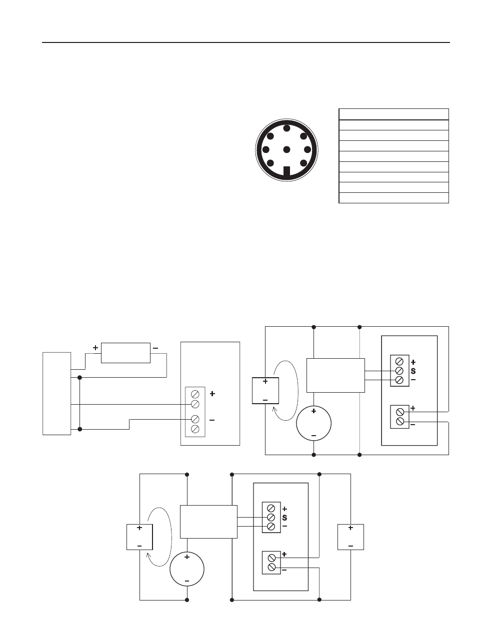
CONNECTIONS
Power and signal connections are provided through the 8-pin
male bulkhead connector on the meter housing (20ft (6m)
cable provided). See the Pin Assignment and Connections
diagrams below.
In addition, it is necessary for proper operation to ground the
unit to a good quality earth ground. Assure negative power
supply is grounded to earth and to the entire electrical/me-
chanical system. If metal piping is used, jumper inlet and
outlet pipes together and connect to ground for best results
in metering accuracy.
2
1
3
7
4
6
5
8
+
_
SEN 1
SEN 2
+
_
12
G
Pin8
Pin2
Pin3
FT520
12 Vdc
power
PE102
Sensor Input
FT420
Power
1
PE102
4-20 mA Device and FT420 with Single Power Supply
Dual Power Supply with Loop Isolation
Pin# Function Color
1
Pulse (-)
White
2
Ground
Brown
3
Pulse (+)
Green
4
4-20 (+)
Yellow
5
Not Used
Grey
6
Not Used
Pink
7
4-20 (-)
Blue
8
Power (+)
Red
Pulse Output Only with FT520
12-15
Vdc
4-20
device
4-20 mA
loop
2
3
4
8
7
+
_
S
+
_
+
_
+
_
+
_
FT420
PE102
12-24
Vdc
4-20
device
4-20 mA
loop
12-15
Vdc
Sensor Input
Power
1
2
3
4
8
7
Cable Plug Contact
Arrangement
Pin1