3 power access p, Anel, 2 fuses – Rola-Chem 554000 ORP/pH Digital Controller User Manual
Page 11: 3 flow switch, 1 dip switches
3.3 Power access P
15
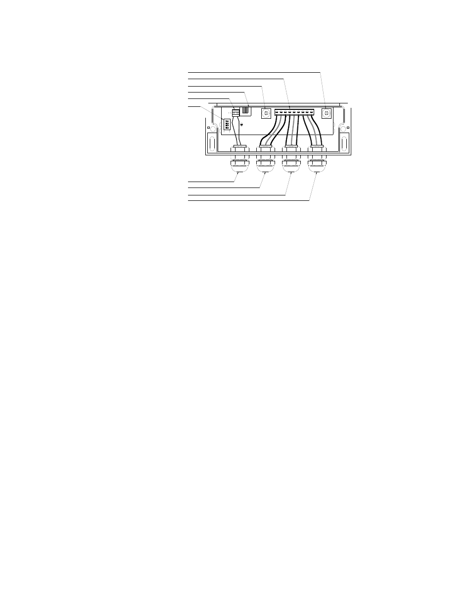
18 EXTERNAL POWER INPUT
13. FLOW SWITCH TERMINAL
14. DIP SWITCH ARRAY
15. FLOW SWITCH INPUT
12. DATA PORT
17. ORP OUTPUT
16. pH OUTPUT
10. TERMINAL STRIP
11. pH FUSE
9. ORP FUSE
17
18
16
12
14
13
FLOW
RS
4
ON
23
1
FUSE
pH
ORP
FUSE
9
9
11
10
anel
f dip switches to control functions that are not normally accessible
s,
tches-
.
.3.2 Fuses
he ORP and pH are independently fused to protect the controller from defective feeders.
ses.
.3.3 Flow Switch
he controller has a flow switch terminal located inside the lower panel on the left side. It is
he flow switch light on the face of the controller is also a power light that shows that the
t, the
3.3.1 Dip switches
The controller has a series o
on the front panel. These dip switches are located inside the Power panel. To access switche
remove power from the controller and remove power access panel. There are four dip swi
#1 is the top switch. The switch is ‘off’ when in the left position and ‘on’ in the right position
See appendix for settings.
3
T
These fuses are located inside the lower panel. The fuse holders are shipped with 5 Amp fu
(Replacement fuses are 5mm x 20mm Fast Acting IEC.)
3
T
shipped with a ‘jumper’ in place. The terminal must either have the jumper or a flow switch
installed.
T
controller is connected to a live power source. If the terminal does not have a closed circui
controller will not turn on.
Rola-Chem Digital Controller PN 554102 6/01/2012 Page: 11 of 20