Instructions for using the flow test kit, Typical tests – Lake Monitors WTA Hydraulic System Analyzer User Manual
Page 3
Model No.
Flow range
Max. Pressure
Temperature range
WTA-32
1.3 – 32 GPM
5 – 120 lpm
6000 psi
420 bar
50 – 180˚F
10 – 80˚C
WTA-50
2– 48 GPM
5 – 180 lpm
6000 psi
420 bar
50 – 180˚F
10 – 80˚C
Connections
By flexible hoses
(2' – 3' recommended length)
Inlet Port: #16 SAE
Outlet Port: #12 SAE
Adapters are available to suit most applications. Consult sales office for details.
Connect the analyzer into the hydraulic system as required using two 2' – 3' long hoses. Ensure
that the flow you wish to measure is passing through the test analyizer in the direction of the
double-arrows on the flow indicator dial. Flow is allowed in the direction of the single arrow, but
this flow will not be measured.
Instructions for using the Flow Test Kit:
1. Open loading valve by rotating counter-clockwise.
2. Start pump momentarily to ensure that oil flows freely through the hydraulic system, then
run pump at maximum speed. Do not change pump speed while turning the loading valve.
3. Slowly close the loading valve to develop the desired pressure. Run the machine until nor-
mal operating temperature is reached i.e. typically 45 - 60°C (110 - 140°F).
4. Open the loading valve to read the flow at minimum pressure.
5. Close loading valve slowly to increase pressure and note reduction of flow as the pressure
is increased to maximum pump pressure to determine pump condition.
10
20
30
40
50
60
70
80
50
75
100
125
150
175
°
F
°
C
10
20
30
40
50
60
70
80
50
75
100
125
150
175
°
F
°
C
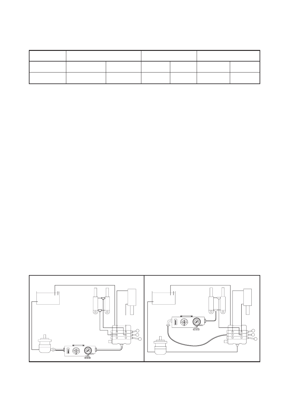
Cylinder
Cylinder
Tank
RFIK
RFIK
Tank
Pump
Pump
Directional
Valve
Test Hose
Relief
Valve
Relief
Valve
Pump Test
Overall System Test
Typical Tests