3 function chart – KROHNE OPTISWITCH 3000C NAMUR EN User Manual
Page 17
The NAMUR output can be switched over to falling or rising
characteristics (see also "Function chart").
The simulation key is located in a recess on the upper side of
the oscillator. Push the simulation key with a suitable object
(screwdriver, pen, etc.).
When the key is pushed, a line break between sensor and
processing unit is simulated. The signal lamp on the sensor
extinguishes. The measuring system must signal a fault and
take on a safe condition when the key is pushed.
Keep in mind that the connected (downstream) instruments will
be activated during operation. This allows you to check the
correct function of the measuring system.
Control lamp (LED) for indication of the switching condition
l
yellow = High current >= 2.2 mA
l
dark = Low current <=1 mA
l
yellow (flashing) = Failure <=1 mA
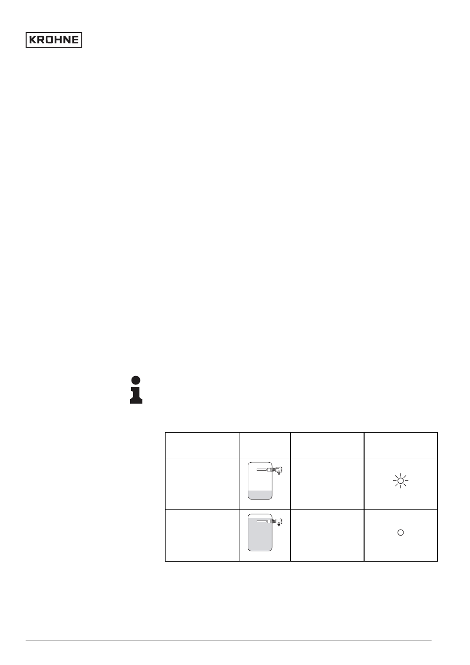
6.3 Function chart
OPTISWITCH 3000 C level switch
The following chart provides an overview of the switching
conditions depending on the adjusted mode and level.
Note:
The mode on the NAMUR amplifier must be set so that the
switching output goes to safe condition in case a fault
message is received (I <=1 mA).
Level
Signal current -
Sensor
Control lamp
Falling characteris-
tics max.
>=2.2 mA
Falling characteris-
tics max.
<=1.0 mA
Simulation key (2)
Signal lamp (5)
OPTISWITCH 3000 C - with NAMUR output
17
Set up
31355
-EN
-060830