Electrical connections – KROHNE OPTISONIC 7300 Quickstart EN User Manual
Page 11
ELECTRICAL CONNECTIONS
3
11
OPTISONIC 7300
www.krohne.com
09/2012 - 4002312801 - QS OPTISONIC 7300 R03 en
3.1 Safety instructions
3.2 Signal cable (remote versions only)
The flow sensor is connected to the signal converter via the signal cable(s). A flow sensor with
one acoustic path, 1 cable is required. A flow sensor with two acoustic paths, 2 cables are
required.
DANGER!
All work on the electrical connections may only be carried out with the power disconnected. Take
note of the voltage data on the nameplate!
DANGER!
Observe the national regulations for electrical installations!
DANGER!
For devices used in hazardous areas, additional safety notes apply; please refer to the Ex
documentation.
WARNING!
Observe without fail the local occupational health and safety regulations. Any work done on the
electrical components of the measuring device may only be carried out by properly trained
specialists.
INFORMATION!
Look at the device nameplate to ensure that the device is delivered according to your order.
Check for the correct supply voltage printed on the nameplate.
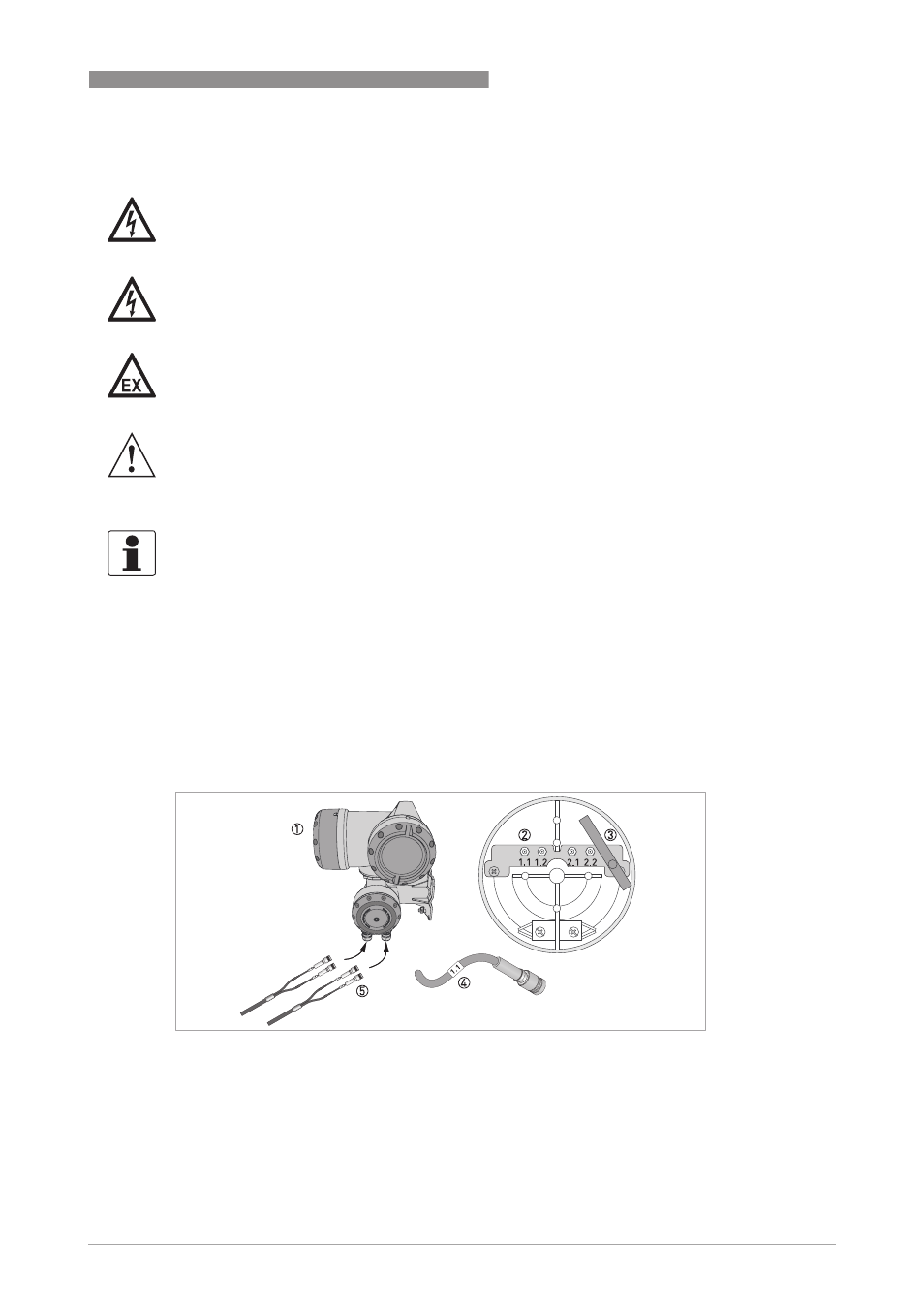
Figure 3-1: Construction field version
1 GFC 300 F converter
2 Open connection box
3 Tool for releasing connectors
4 Marking on cable
5 Insert cable(s) into connection box