Arcam Preamp Processor AV8 User Manual
Page 22
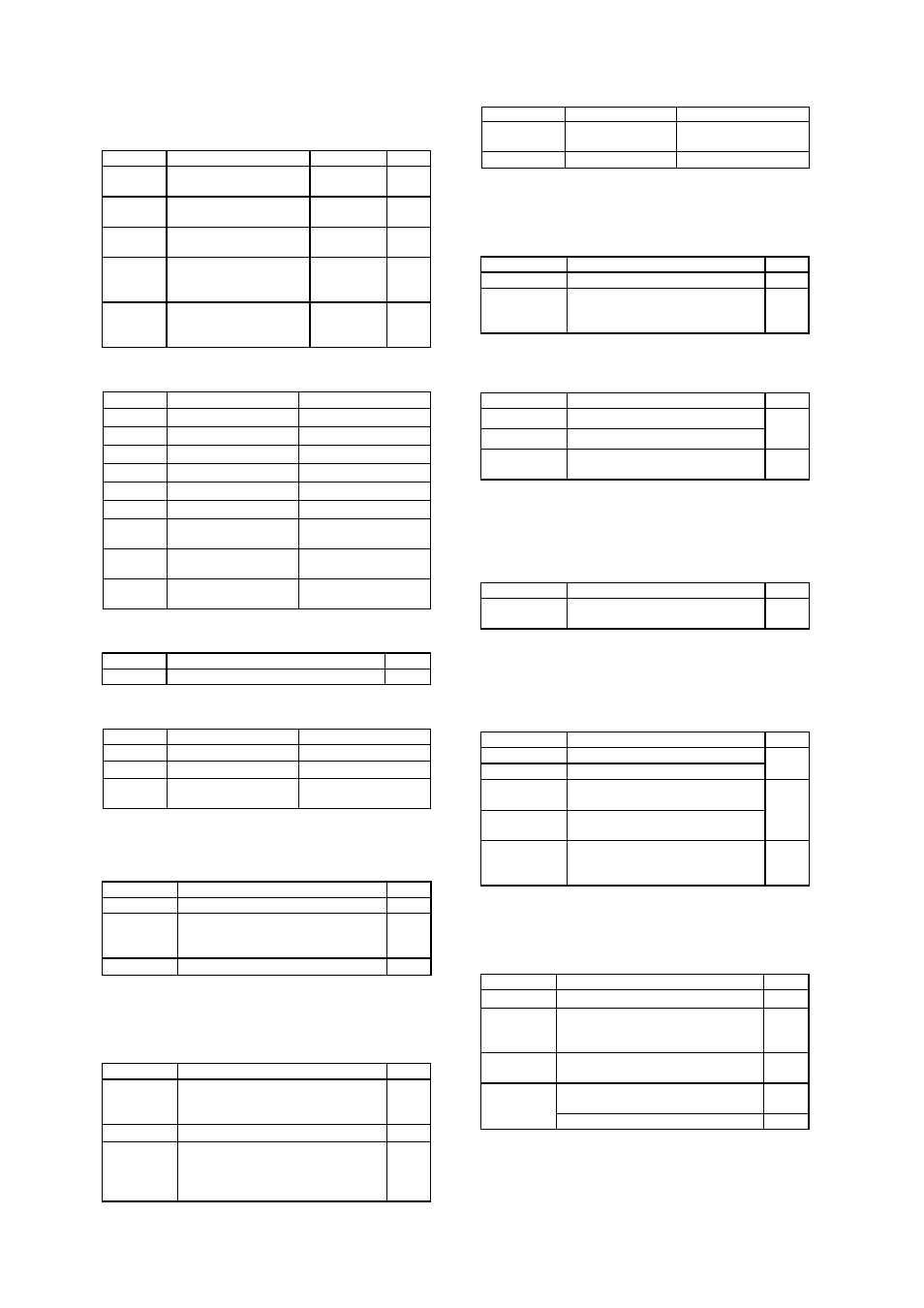
15.
Fit the digital PCB (L896AY) such that the notch in
the board is by the headphone board. Once the pcb is in place, fit
the cables below. See FIG9.
Part No.
Description
Reference
Qty
H039
M3x38mm mf pillars
into standoffs
7
H030
M3x18mm mf pillars
into standoffs
4
L931CA
30-way foil cable from
digital to display 190mm
SK901 1
L923CA
8-way AMP CT from
digital to phase lock loop
120mm
SK903 1
L933CA
5-way AMP CT from
digital to phase lock loop
100mm
SK801 1
Connect the cable assemblies listed below.
Part No.
From
To
L923CA
Audio / SK914
Digital / SK102
L923CA
Audio / SK913
Digital / SK103
L933CA
Audio / SK915
Digital / SK100
L922CA
Audio / SK916
Digital / SK902
L931CA
Video / SK702
Digital / SK900
L929CA
Vertical Power / SK8
Digital / SK1002
L925CA
Horizontal Power /
SK6
Digital / SK1001
L926CA
Horizontal Power /
SK7
Digital / SK1003
L928CA
Horizontal Power /
SK2
Digital / SK1000
16.
Fit the phase lock loop PCB (L948AY). See FIG9.
Part No.
Description
Qty
H030
M3x18mm mf pillars into standoffs
4
Connect the cable assemblies listed below.
Part No.
From To
L923CA
Digital / SK903
Phase lock loop / SK1
L933CA
Digital / SK801
Phase lock loop / SK3
L925CA
Horizontal Power /
SK4
Phase lock loop / SK2
17.
Clip 2 F219 cable clips into top of EMC shield. Then
using the cable clips as handles fit EMC digital PCB shield.
Refer to FIG9.
Part No.
Description
Qty
E919MC
Digital EMC Shield
1
HA3V06A
Screw Machine M3x6mm Pan Torx
Steel Zinc-Plate Clear into standoffs
thro’ EMC shield into pillars
11
F219
Twist Lock cable clip
2
18.
Assemble the rear panel to the chassis using all the
screws in italics on previous pages. Fit the power can lid over
the chassis and the vertical can wall with vents directly above the
EMC can on the power board. See FIG10.
Part No.
Description
Qty
HF4V09B Screw
Self-Tapping-SEMS
No4x9mm
Pan Torx-Slot Steel Zinc-Plate Black
(rear chassis return)
6
E877MC
Power Can Lid
1
HF4V09B Screw
Self-Tapping-SEMS
No4x9mm
Pan Torx-Slot Steel Zinc-Plate Black
(2 into power can wall and 2 into
chassis wall)
4
Connect the cable assemblies listed below.
Part No.
From To
L939CA
IEC Inlet
Horizontal Power /
SK1
L925CA
Audio / SK901
Aux snap-off / SK927
19.
Assemble the phono can assembly to the chassis (3
screws) and the rear panel (1 screw) making sure the cable loom
fits into notch in top of the phono can. See FIG11.
Part No.
Description
Qty
E041AY Phono
Can
Assembly
1
HF4V09B Screw
Self-Tapping-SEMS
No4x9mm Pan Torx-Slot Steel
Zinc-Plate Black
4
20.
Assemble the display PCB to the fascia assembly
Part No.
Description
Qty
E919AY Fascia
Assembly
(silver)
E919AYB
Fascia Assembly (black)
1
HA3V06A
Screw Machine M3x6mm Pan Torx
Steel Zinc-Plate Clear into standoffs
14
21.
Assemble the fascia assembly and the display PCB to
the chassis. Check the operation of mains button at this stage.
Keep the foil bent upwards. Connect the flexfoil after the fascia
assembly is fitted to the chassis.
Part No.
Description
Qty
HE6V06B
Self Tapping No6x6mm Pan Torx-
Slot Steel Zinc-Plate Black
4
Connect L931CA from the digital board (SK901) to the display
board (SK100).
22.
Assemble the cover plate to the chassis
Part No.
Description
Qty
E826CP
Cover Plate (Silver)
E826CPB
Cover Plate (black)
1
HA4V06S
Screw Machine M4x6mm Pan Torx
St Steel Nickel
HA4V06B
Screw Machine M4x6mm Pan Torx
St Steel Black
4
HF4V09B Screw
Self-Tapping-SEMS
No4x9mm Pan Torx-Slot Steel
Zinc-Plate Black
4
23.
Fit the Phono Board Upgrade Kit, using L870AY
board and the following parts. See FIG12 for assembly
instructions.
Part No.
Description
Qty
H031
20 ff pillars
3
HF4V09B Screw
Self-Tapping-SEMS
No4x9mm Pan Torx-Slot Steel Zinc-
Plate Black into rear panel
1
HA3V06A
Screw Machine M3x6mm Pan Torx
Steel Zinc-Plate Clear into pillars
6
8-way AMP CT from phono (SK2) to
audio (SK901) 280mm
1
L925CA
8-way connector
2