Figure #4 – Detcon FP-424C User Manual
Page 10
d) Replace the plug-in transmitter module and the junction box cover.
5.6 Remote Mounting Applications
Some sensor mounting applications require that the gas sensor head be remotely mounted away from the
sensor transmitter. This is usually true in instances where the gas sensor head must be mounted in a loca-
tion that is difficult to access. Such a location creates problems for maintenance and calibration activities.
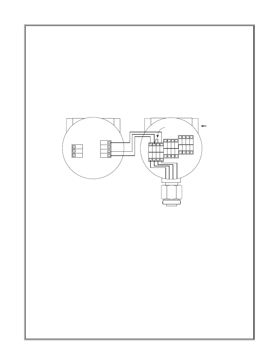
Detcon provides the FP-424C sensor in a remote-mount configuration in which the sensor (Model FP-424C-
RS) and the transmitter (Model FP-424C-RT) are provided in their own condulet housing and are interfaced
together with a three conductor cable. There is a limit 0.5 ohm maximum resistance drop per wire over the
seperation distance.
Ω
Reference figure 4 for wiring diagram. Also note the jumper that is required on the remote sensor terminal
connector board. Failure to install this jumper will cause a sensor fault condition.
Remote Mounting Configuration - Bridge Voltage Adjustment
When a sensor is remotely mounted away from the transmitter, consideration must be given to the lengths
of cable used and how it affects the sensor bridge voltage. Differing lengths of cables will have varying
amounts of resistance which will shift the sensor bridge voltage. Because of this, the bridge voltage will
need to be adjusted after initial power up. This adjustment is only required after initial installation and will
not be necessary thereafter, even in the event of replacement of the plug-in sensor. See section 6.1 for
instructions.
6.0 S
TART UP
Upon completion of all mechanical mounting and termination of all field wiring, apply system power and
observe the following normal conditions:
a) Detcon electronic controller “Fault” LED is off.
b) A temporary upscale reading will occur as the sensor powers up.
6.1 Remote Mount Bridge Voltage Set
If the sensor has been installed using the remote mounting configuration as described in section 5.6, the
sensor bridge voltage must be adjusted after initial power up. If this is not the case skip this section and
proceed to Initial Operational Tests. Otherwise follow the steps below to set the sensor bridge voltage.
Detcon Model FP-424C Combustible Gas Sensor PG.10
1 2 3 4
W
H
T
B
L
K
Y
E
L
B
LU
Install
Jumper
Remote Transmitter
FP-424C-RT
Remote Sensor
FP-424C-RS
Measure Bridge Voltage
From White (1) to Blue (4)
Target voltage is 2.7v
WHT
BLK
YEL
BLU
Plug unused port
with 3/4 NPT plug.
Figure #4