WEN 3710 10 inch Table Saw ver.2011 User Manual
Page 16
16
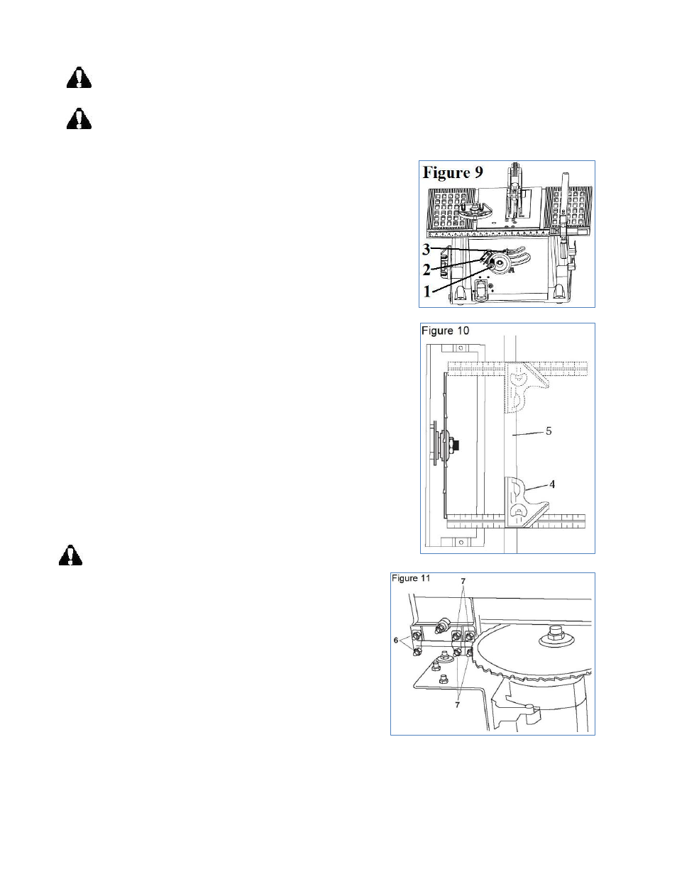
Blade Parallel to Miter Gauge Groove Adjustment
(Figure 9, 10 & 11)
Warning: To prevent personal injury, always disconnect the plug from power source before
making any adjustments.
Warning: If the blade is misaligned by more than 1/8", do not attempt to align or operate the
saw. Have a qualified service technician perform blade alignment.
1. Move the blade guard out of the way.
2. Raise the blade to the maximum height by turning the hand
wheel (1, Figure 9) counterclockwise. Push in the hand wheel
(1, Figure 9) and tilt the blade to 0°, then lock in place with
the bevel locking lever (3, Figure 9).
3. Select a tooth with a ―right set‖ on the end of the blade
closest to you. Mark it with a marker.
4. Place a combination square base (4, Figure 10) against the
left side of the right miter gauge groove (5, Figure 10).
5. Adjust the rule so it touches the front marked tooth. Lock the
ruler so it holds its position in the square assembly.
6. Rotate the blade bringing the marked tooth to the rear and
about 1/2" (13 mm) above the table.
7. Carefully, slide the combination square to the rear until the
ruler touches the marked tooth.
8. If the ruler touches the marked tooth at the front and rear
positions, no adjustment is necessary.
If the front and rear measurements are not the same, blade is not
parallel to the miter slot. Proceed to steps 9 –19 to perform the
adjustment.
9. Remove the combination square and stand the saw on its left
side so you can access the six adjustment nuts (6 & 7 Figure
11) that secure the axis rod to the table. Make sure the table
is secure.
Warning: Place folded pieces of cardboard over the blade
to protect your hands.
10. Us a 10 mm wrench to loosen all eight adjustment nuts
about 1/2 turn each.
11. Place the saw in the upright position.
12. Carefully move the blade to the left or right until it is
aligned properly.
13. Check the alignment with the combination square
(repeat steps 4 – 7).
14. Tighten the two front adjustment nuts (6, Figure 11).
Reach under the front and rear of the table with a
wrench to access these nuts.
15. Re-check the alignment. If additional adjustment is required, loosen only the two front adjustment
nuts (6, Figure 11) and repeat steps 4 & 5 until the blade is parallel to the miter slot. Tighten the
two front adjustment nuts (6, Figure 11).