Power max 560 tile cutter, Fig.b fig.a fig.c fig.d – Vitrex WS560180 User Manual
Page 3
Power Max 560 Tile Cutter
04
05
Tel: +44 (0) 1253 789180
Tel: +44 (0) 1253 789180
grounding plugs and 3-hole socket that accept the tools
plug.
Repair or replace damaged or worn cord immediately.
To avoid the possibility of the appliance plug or socket
getting wet, position the tile cutter to one side of a wall
mounted receptacle to prevent water from dripping onto
the socket or plug. The user should arrange a ‘drip loop’ in
the cord connecting the saw to thesocket. The ‘drip loop’
is that part of the cord below the level of the socket, or the
connector if an extension cord is used, to prevent water
travelling along the cord and coming into contact with the
socket.
If the plug or socket does get wet, DONT unplug the cord.
Disconnect the fuse or circuit breaker that supplies power
to the tool. Then unplug and examine for presence of
water in the socket.
Only CE Listed extension cords should be used with this
product.
Improper use of extension cords may cause inefficient
operation of your tool, which can result in overheating.
Be sure your extension cord is rated to allow sufficient
current flow to the motor.
Do not let your fingers touch the terminals of the plug when
installing or removing the plug to or from the outlet.
If not properly grounded, this power tool can incur the
potential hazard of electrical shock particularly when used
in damp locations or in proximity to plumbing.
If an electrical shock occurs, there is the potential of a
secondary hazard such as your hands contacting the cutter
blade.
FEATURES OF THE CUTTER
• High – torque direct drive industrial motor
• Ø180 x 16 mm diamond blade cuts tile up to 33mm thick.
• Detachable splash guard is designed for quick blade
installation.
• Adjustable rip and mitre guides allow users to make 90o
rip cuts and 0˚-45˚ mitre cuts on both right and left side.
• The right cutting table is hinged to work as an adjustable
mitre block for 22.5˚, 30˚ and 45˚ mitre cuts.
• The right cutting table has a built – in water reservoir for
cooling the blade.
• The water reservoir contains a side overflow hole to
ensure the proper water level.
• The built – in handle helps users to carry the portable tile
saw easily from place to place.
• Power cord and rip guide can be stored in bottom
storage to prevent the accessories loss or damage.
UNPACKING
ASSEMBLY AND SETUP
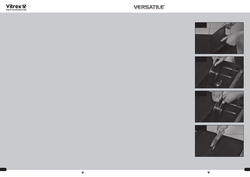
Placing the blade:
Place the blade onto the shaft, pushing it against the inner
flange. Make sure the side of the blade with directional
arrow is facing towards you. Next place the outer flange
and blade shaft nut, and then tighten the blade shaft nut.
Make sure the nut is firmly tightened with enclosed
spanner provided. DO NOT OVER – TIGHTEN!
(See Fig A-C)
Placing The Splash Guard
Insert guard support into the socket. Make sure the
support is parallel to the blade. Place splash guard onto
support and tighten wing nut. (See Fig D)
Place the Rip Guide on the top of the cutting table and
clamp both ends. Rip guide can be placed on both right and
left side. (See Fig E)
Place the Mitre Guide onto the Rip Guide. The mitre guide is
designed to attach to rip guide. Therefore users use mitre
guide on both right and left side. (See Fig F)
SAW OPERATION
Take out the electrical cord to connect to the power source.
The electrical cord is stored underneath the counter.
Detach the splash guard, and then open the right cutting
table to fill the reservoir with water to the recommended
level. ATTENTION! Keep water level with lines. (See Fig G)
Attach the splash guard above the blade and close to the
right cutting table.
Now you are ready to cut!
Steps for rip, angle and mitre cuts :
The edge of the cutting table (upper frame) is marked
with rigid dimension in both inches and centimetres for
accurate cutting.
For 90˚ rip cuts, after the rip guide is positioned for the
desired dimension, lean the material against the rip guide
then push the material forward to the blade. (See Fig H)
For 0˚ – 45˚ angle cuts, attach the mitre guide on the rip
guide. Choose the degree you want and tighten the
adjustment knob. Then push the mitre guide and material
together forwards for the blade to cut the material.
(See Fig I)
For mitre cuts raise the right cutting table at the desired
angle, you can choose 22.5˚, 30˚ and 45˚. Put the two
stands into the grooves to hold the cutting table in place.
Place the material face down onto the left cutting table and
you are ready to cut. (See Fig J)
TILE CUTTER MAINTENANCE
WARNING:
Do not service, clean or maintain the tile cutter without first
turning off the motor and unplugging the tile cutter from its
power source. Failure to do so may result in serious injury
to the operator.
Always clean the tile cutter after each use and store in dry
conditions.
Wipe off all exterior surfaces and keep the cutting table
clean and free of all debris.
Always let the blade cut at its own speed. Do not force the
material being cut.
Always check the blade for signs of damage.
Always store the electrical cord underneath the saw after
use.
Always keep water level at the recommended level.
DO NOT let the saw run dry!
Never attempt to service the internal parts of the motor by
yourself as this will void your guarantee
FIG.B
FIG.A
FIG.C
FIG.D
ELECTRICAL REQUIREMENTS
CONNECTING TOOL TO POWER SOURCE OUTLET. This
machine source must be earthed while in use to protect
the operator from electrical shock.
In the event of a malfunction or breakdown, grounding
provides a path of least resistance for electrical current
to reduce the risk of electrical shock. The plug must be
plugged into a matching outlet that is properly installed
and grounded in accordance with all local codes and
ordinances.
Do not modify the plug provided if it will not fit the outlet.
Have the proper outlet installed by a qualified
electrician.
Improper connection of the equipment – grounding
conductor can result in a risk of electric shock. The
conductor with insulation having an outer surface that is
green (with or without yellow stripes) is the
equipment grounding conductor. If repair or
replacement of the electric cord or plug is necessary, do
not connect the equipment – grounding conductor to a
live terminal.
Check with a qualified electrician or service personal if
the grounding instructions are not completely
understood, or if in doubt as to whether the tool is
properly grounded.
Use only 3 – wire extension cords that have 3 – prong