Video Mount Products LCD-PV User Manual
Page 4
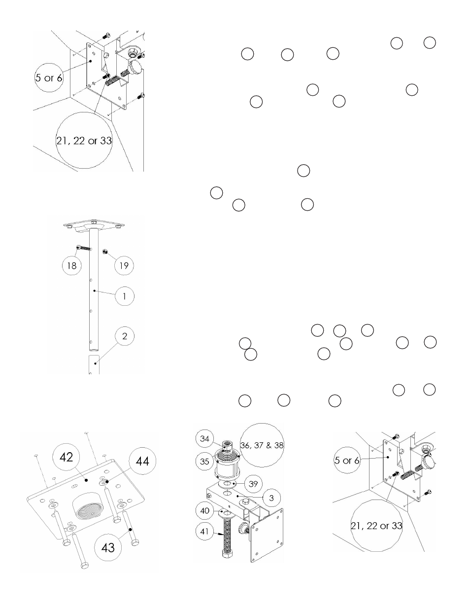
Step 6
Attach your monitor to the chosen mounting plate
(#5
or
#6)
using the M4
(#21)
, M5
(#22)
or M6
(#33)
screws as appropriate.
Step 7
Connect the extension tube
(#2)
to the ceiling plate
(#1)
using
the 5/16” screw
(#18)
and nylon nut
(#19)
. Proceed to step 12
If you plan to use 1.5” NPT as a ceiling mast:
Step 8
Mark the ceiling or desired mounting surface in preparation of
installation of ceiling plate
(#42)
. If mounting to wooden ceiling
joists, pre drill pilot holes using a 7/32” drill bit. Attach the ceiling
plate
(#42)
to the wooden ceiling joist using the 5/16” by 2.5” long
lag screw
(#43)
and washer
(#44)
. WARNING: Please verify that
your mounting surface will support the combined weight of your
mount, mounting hardware, and flat panel. Also verify that the
mounting surface is safe to drill through. Please note only mount-
ing hardware for mounting to wooden ceiling joists will be pro-
vided with the unit. If mounting to a surface other than wooden
ceiling joists then other hardware will be required. If in doubt or
uncertain about any of the above, please contact a professional
installer.
Step 9
Attach the female pipe couple
(#37
,
#38
&
#36)
to the top of the
support tube
(#3)
using the 5/8” screw
(#41)
, washers
(#39
&
#40)
,
spring washer
(#35)
and hex nut
(#34)
.
Step 10
Attach your monitor to the chosen mounting plate
(#5
or
#6)
using the M4
(#21)
, M5
(#22)
or M6
(#33)
screws as appropriate.
Step 6: Attaching the monitor
(monitor not included)
42
43
42
44
Step 7: Connecting the ceiling
plate and the extension tube
Step 8: Mounting the ceiling plate
Step 9: Attaching the female
pipe couple
Step 10: Attaching the monitor
(monitor not included)
6
5
22
21
33
1
2
19
18
37
36
38
3
41
40
39
35
34
5
6
21
22
23