Enjoy your mount – Video Mount Products ER-148-4PKIT User Manual
Page 3
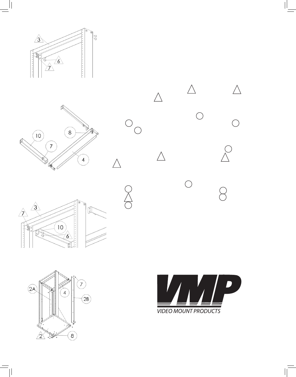
Step 1
Before starting lay out all parts to your mount and match them to
the parts list provided. Verify that you have all your parts before
attempting to assemble the mount. Also before attempting to as-
semble the ER-148-4PKIT you should have already assembled the
ER-148. Note: ER-148-4PKIT part numbers are in circles and ER-148
part numbers are in triangles.
Step 2
Remove the ¼” – 20UNC screws
#6
ER-148 and nuts
#7
ER-148 from
the Support Plate
#3
ER-148.
Step 3
Attach the two Connector Plates
#10
ER-148-4PKIT to the Support
Plate
#4
ER-148-4PKIT using the ¼” – 20UNC screws
#7
ER-148-4PKIT
and nuts
#8
ER-148-4PKIT.
Step 4
Attach the other end of the Connector Plate
#10
ER-148-4PKIT to
the Support Plate
(#3
ER-148 using the screws
(#6
ER-148 and nuts
(#7
ER-148 removed in step 2.
Step 5
Attach the Left Support “L”
(#2A
ER-148-4PKIT and Right Support
“L”
(#2B
ER-148-4PKIT to the Support Plate
(#4
ER-148-4PKIT and
Base
(#2
ER-148 using the ¼” -20UNC screws
(#7
ER-148-4PKIT and
nuts
(#8
ER-148-4PKIT. Note: It is easier to attach the “L” Supports if
you have all the screws lightly secured until all screws are in place
and then tighten them down.
Please verify that all nuts and screws are securely tightened.
Step 2: Removing screws from
support plate
Step 3: Attaching the connector
plates to the support plate
WARNING: The installer of these products must verify that the
mount surface, ceiling or wall, will safely support the combined
weight of all attached equipment and hardware. Video Mount
Products will not be held liable for the improper use or installation
of its products.
Enjoy Your Mount!
Step 4: Attaching the connector
plates to the ER-148
Step 5: Attaching the rear
support rails
10
2B
7
8
4
2A
8
3
6
7
10
4
7
6
7
3
2