Enjoy your mount – Video Mount Products PDS-LFTB User Manual
Page 3
Step 1
Before starting, lay out all parts to your mount and match them to
the parts list provided. Verify that you have all your parts before
attempting to assemble the mount.
Step 2
Mark the wall or desired mounting surface in preparation of instal-
lation of wall plate . If mounting to wooden studs, pre drill pi-
lot holes using a 7/32” drill bit. Attach the wall plate to the
wooden stud using the 5/16” by 2.5” long lag screw and washer
making sure the small ear f aps are on the top rail of the wall
plate . WARNING: Please verify that your mounting surface
will support the combined weight of your mount, mounting hard-
ware, and fl at panel. Also verify that the mounting surface is safe
to drill through. Please note only mounting hardware for mount-
ing to wooden studs will be provided with the unit. If mounting to
a surface other than wooden studs then other hardware will be
required. If in doubt or uncertain about any of the above, please
contact a professional installer.
Step 3
Determine the correct screw size and if you need to use washers,
lock washers, or spacers. Note: Spacers are used for TVs with re-
cessed hole patterns.
Secure the TV to the screen mount bracket
using the appropriate hardware through .
Note: The
brackets have to be level with each other to work properly..
Step 4
Use the hooks in the wall pivot bracket to hook on the top rail of
the wall plate . Use the M5 screws to secure the f at panel
to the wall plate and to secure its horizontal position.
Step 5
To adjust tilt, loosen the handles and grasp the top and bottom
of the f at panel and pull the f at panel into position. After achieving
desired tilt retighten the handles. If obstruction prevents full rotation
of the handle pulling out the handle will allow rotation of handle
without affecting the tension of the mount. Push the handle back
down when to wish to adjust the tension further. Use this ratcheting
motion to tighten the tilt mechanism.
Please verify that all nuts and screws
are securely tightened.
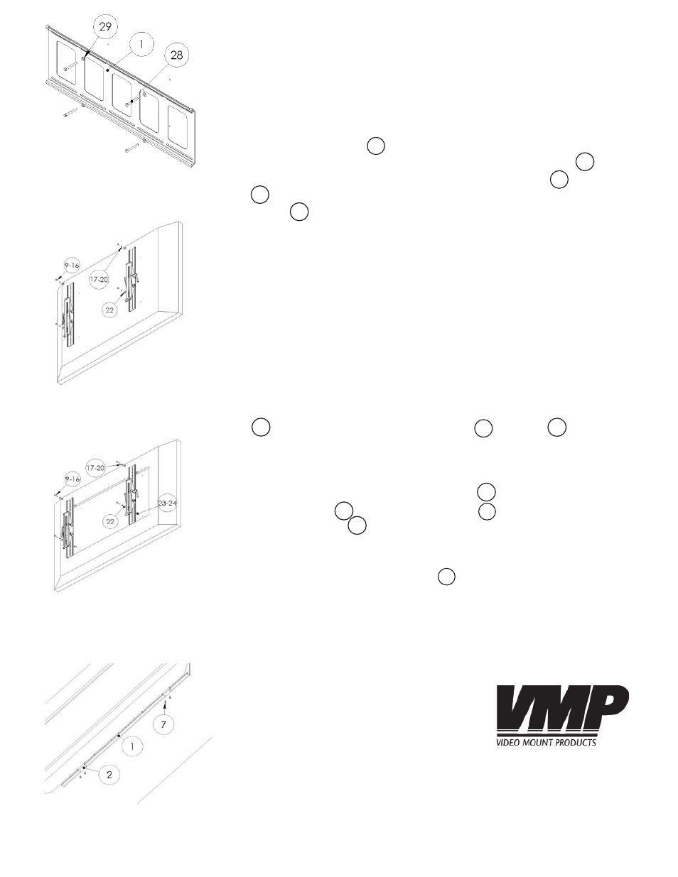
Step 2 : Attaching the wall plate
to the wall
Step 3A: Attaching the mounting
rails (holes are not recessed)
Step 4 : Attaching the mounting
rails to the wall plate
Step 3B: Attaching the mount-
ing rails (holes are recessed)
27
13
WARNING: The installer of these products must verify that the mount
surface, ceiling or wall, will safely support the combined weight of
all attached equipment and hardware. Video Mount Products will
not be held liable for the improper use or installation of its products.
Enjoy Your Mount!
3
2
12
1
1
29
28
1
1
1
10