Enjoy your mount – Video Mount Products FP-SFTB User Manual
Page 3
Step 1
Before starting, lay out all parts to your mount and match them to
the parts list provided. Verify that you have all your parts before
attempting to assemble the mount.
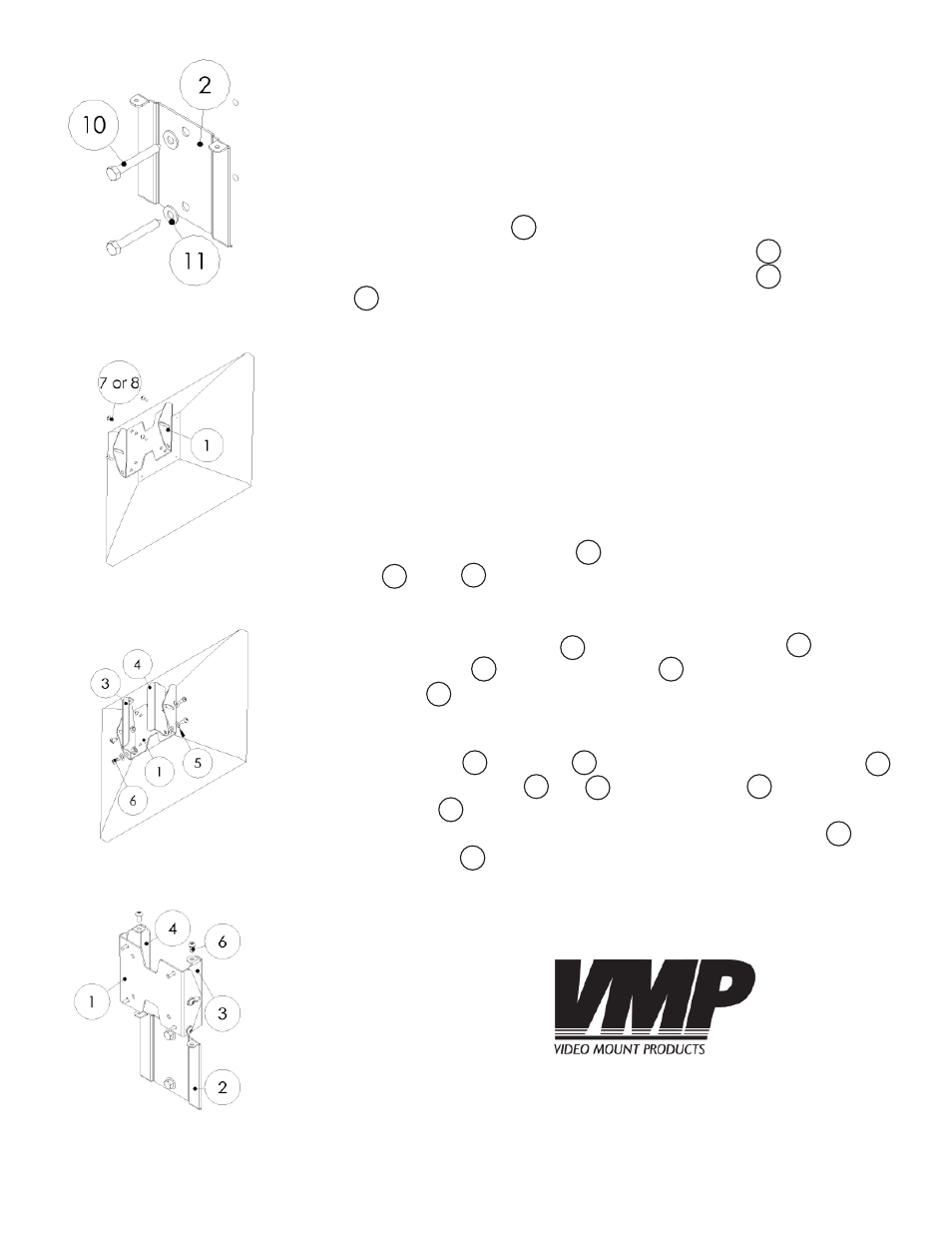
Step 2
Mark the wall or desired mounting surface in preparation of instal-
lation of wall plate . If mounting to wooden studs, pre drill pilot
holes using a 7/32” drill bit. Attach the wall plate to the wood-
en stud using the 5/16” by 2.5” long lag screw and washer
making sure the tabs with the thread holes on the wall plate
are at the top of the wall plate. WARNING: Please verify that your
mounting surface will support the combined weight of your mount,
mounting hardware, and fl at panel. Also verify that the mounting
surface is safe to drill through. Please note only mounting hard-
ware for mounting to wooden studs will be provided with the unit.
If mounting to a surface other than wooden studs then other hard-
ware will be required. If in doubt or uncertain about any of the
above, please contact a professional installer.
Step 3
Attach the mounting plate to the back of the monitor using the
M4 or M5 screws provided with the FP-SFT.
Step 4
Attach the left side wall to the mounting plate using the
nylon washers and security screws . Do the same for the right
side wall .
Step 5
Slide the left and right side walls behind the wall plate .
Secure the side walls and to the wall plate using the secu-
rity screws . To adjust the tilt tension simply tighten or loosen the
security screws located in the arcs of the mounting plate using
the allen key .
Please verify that all nuts and screws are securely tightened.
Step 2: Attaching wall plate
to the wall
Step 3: Attaching fl at panel to
mounting plate
WARNING: The installer of these products must verify that the mount
surface, ceiling or wall, will safely support the combined weight of
all attached equipment and hardware. Video Mount Products will
not be held liable for the improper use or installation of its products.
Enjoy Your Mount!
2
6
5
Step 4: Attaching the left and
right side walls
Step 5: Securing the tilt
mechanism to the wall plate
(LCD not shown for clarity)
1
9
3
2
1
8
7
10
1
2
4
11
3
4
2
3
4
6