Et-314, Application circuit, Version 1.2 – USGlobalsat ET-314 User Manual
Page 8
ET-314
The Specifications are subject to be changed without notice. Copyright © 2007, GlobalSat Technology.
Page 8 of 19
Version 1.2
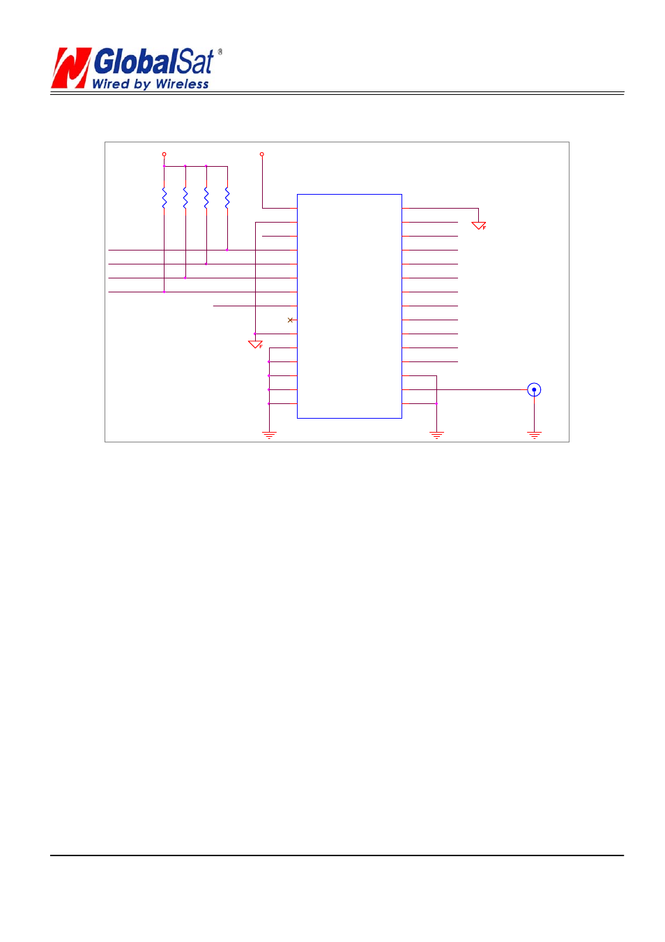
Application Circuit
GPIO_0
ACTIVE ANT
1
2
GPIO_14
V_BAT
GPIO_5
TXA
TXB
GPIO_10
VCC
VCC_RF
1PPS
RXB
V_ANT
GPIO_1
GPIO_15
50 ohm microstrip line
VCC
R1
10k
1
2
R2
10k
1
2
GPIO_13
RESET
RXA
BOOT
U1
GPS
6
30
27
28
29
5
4
3
2
1
7
8
9
10
11
12
13
14
15
26
25
24
23
22
21
20
19
18
17
16
TXB
GND
GPIO_13
GPIO_15
1PPS
TXA
RXA
Bootselect
GND
VCC
RXB
GPIO_14
RF_ON
GND
A_GND
A_GND
A_GND
A_GND
A_GND
GPIO_0
GPIO_5
GPIO_1
GPIO_10
NRESET
V_BAT
VCC_RF
V_ANT
A_GND
RF_IN
A_GND
R4
10k
1
2
R3
10k
1
2
(1) Ground Planes:
ET-314 GPS receiver needs two different ground planes. The GND_A pin(11、
12、13、14、15、16、18) shall be connect to analog ground. The GND pin(2、
10、30) connect to digital ground.
(2) Serial Interface:
The Serial interface pin(RXA、TX1、TXB、RXB) is recommended to pull up(10KΩ).
It can increase the stability of serial data.
(3) Backup Battery:
It’s recommended to connect a backup battery to V_BAT.
In order to enable the warm and hot start features of the GPS receiver. If you don’t intend to use a
backup battery, connect this pin to GND or open.
If you use backup battery, shall need to add a bypassing capacitor (10uF) at V_bat trace. It can
reduce noise and increase the stability.
(4) Antenna:
Connecting to the antenna has to be routed on the PCB. The transmission line must to controlled