Application, Application circuit – USGlobalsat EB-5635RE User Manual
Page 7
2012/7/30
- 7 -
Application
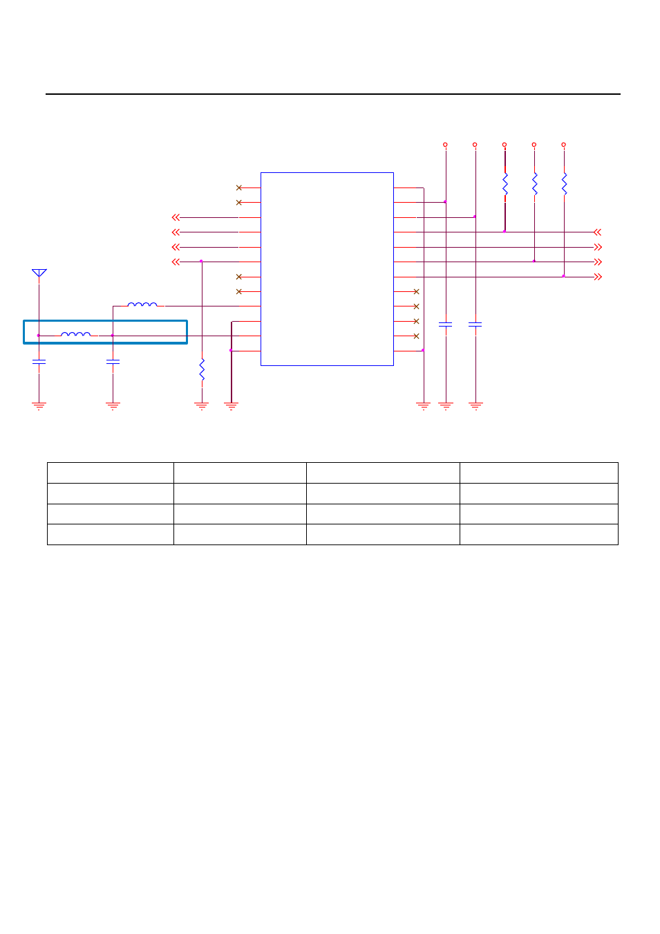
Application Circuit
M1
EB-5365RE
NC
1
NC
2
TIMEMARK
3
GPIO
4
WAKE_UP
5
ON_OFF
6
NC
7
NC
8
VCC_RF
9
GND
10
RF_IN
11
GND
12
GND
13
NC
14
NC
15
NC
16
NC
17
DR_I2C_DIO
18
DR_I2C_CLK
19
TXD
20
RXD
21
VBAT
22
VCC
23
GND
24
R3
2K2/NC
R4
2K2/NC
1V8
1V8
DR_I2C_DIO
RD_I2C_CLK
ON_OFF
WAKE_UP
GPIO
L2
CHOKE RF
GPS_3V3
R1
10K
1PPS OUTPUT
VBAT
GPS_ANTENNA
1
C9
CAP NP
C8
CAP NP
C10
10UF
C7
10UF
3V3
50ohm LINE
TXA
RXA
R2
10K/NC
1
2
L5
33N/NC
GPS Active Antenna Specifications (Recommendation)
Frequency:
1575.42 + 2MHz
Amplifier Gain:
18~22dB Typical
Axial Ratio:
3 dB Typical
Output VSWR:
2.0 Max.
Output Impedance:
50Ω
Noise Figure:
2.0 dB Max
Polarization:
RHCP
Antenna Input Voltage:
3.3V (Typ.)
NOTE
1. TIMEMARK: One pulse per second output. When EB-5365RE is 3D Fixed, this pin will output
1uS Hi level pulse. If don
’t use this, just NC.
2. GPIO: User can use this I/O pin for special functions. For example, control LED, and can be
used External Interrupts. If don
’t use this, just NC.
3. WAKE_UP: EB-5365RE power on, WAKE_UP will output 1.8V.
4. ON_OFF: This pin is controlled EB-5365RE power on. If EB-5365RE want to EB-365 pin to pin
compactable, please ON_OFF connect to WAKE_UP. If don
’t use this, just NC.
5. DR I2C interface: The I2C interface supports required sensor instruments such as gyros,
accelerometers, compasses or other sensors that can operate with an I2C bus. If don
’t use
this, just NC.
6. VBAT: This is the battery backup power input for the SRAM and RTC when main power is
removed. VBAT is 2V ~ 3.5V.
7. EB-5365RE RF is has 3.3V external POWER to active ANTENNA use.