Static switches, Series ss, Series specific information 6u – Schaefer Series SS User Manual
Page 4
www.schaeferpower.de
Inverters
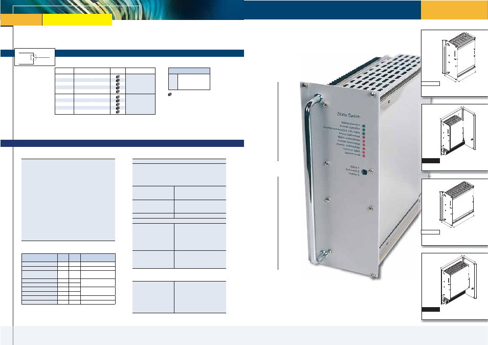
Static Switches
with 1-phase output from 0.8 to 10kVA
AC output
AC supply 1
AC supply 2
static switch
1-phase
Inverters
Frequency Designation
.4
.5
.6
.8
400 Hz
50 Hz
60 Hz
800Hz
= natural convection
Model
Output Power [kVA]
Cooling
Input / Output [V]
SS 1506
SS 3506
SS 3516
SS 3526
SS 3536
0.8
1.6
3
5
10
115
SS 1508
SS 3508
SS 3518
SS 3528
SS 3538
0.8
1.6
3.2
5
10
230
Series SS
Static Switches
Series specific information
6U
Eurocassette
(pluggable module for 19“ sub-rack)
Wall mount
21TE
6U
166.5 mm
140 mm
360 mm
260 mm
approx. 3.3 kg
approx. 6.3 kg
series SS 15xx
series SS 15xx
Standard
Optional
Eurocassette
(pluggable module for 19“ sub-rack)
Standard
21TE
6U
226 mm
approx. 5.0 kg
series SS 35xx
Optional
Wall mount
140 mm
360 mm
260 mm
approx. 8.0 kg
series SS 35xx
Function
The Static Switch has two inputs for load supply, a priority and a non-
priority input, and synchronizes the frequency of one supply to the
other. Typically, but not exclusively, supplied by Mains and an Inverter,
there are 3 modes of operation:
1. Service mode Mains - mains is selected as the load provider.
2. Service mode Inverter - inverter is selected as the load provider.
3. Automated function with priority selection.
In the automated function the supply of the priority input is connected
to the load. If the static switch detects deviation from tolerance through
monitoring, it will transfer the load to the non-priority input. When the
supply of the priority input has returned to be within parameters of
voltage and frequency, the static switch reverses this selection.
For adapting the static switch to different requirements, the priority
for mains or inverter operation can be selected externally via an opto-
coupler. The static switch can also be inhibited via another opto-coupler
for disconnecting the load. LEDs and potential-free relay contacts
indicate the mode of operation and / or the status of alarms.
Indication of operation mode
Input / Output
Surge current
5 x I
nom
for 1 s
Overload protection
For models with I
nom
≤ 15 A: short circuit
protected: unit switches off at output
current above 15 A;
For models with I
nom
> 15 A: an external
fuse with slow characteristic is required
Inhibit (remote on / off)
logic low = 0 – 5 V;
logic high = 12 – 30 V
via opto-coupler
Priority selection
logic low = 0 – 5 V;
logic high = 12 – 30 V
via opto-coupler
Transfer trigger
0.8 x U
nom
< voltage < 1.15 x U
nom
Transfer time
- mains to inverter (mains
priority) or inverter to
mains (inverter priority)
For models with I
nom
≤ 15 A:
≤ ½ period, typically ¼ period
(including failure detection time)
For models with I
nom
> 15 A:
one period, typically ½ period
(including failure detection time)
- return to mains (mains
priority) or return to
inverter (inverter priority)
For models with I
nom
≤ 15 A:
practically no interruption
For models with I
nom
> 15 A:
typically ½ period
Options
Mechanics / environment
■
19” sub-rack for eurocassette,
refer to page 121
■
Wall mount
■
Increased mechanical strength
■
Tropical protection
■
Extended temperature range to
–40 °C
Green
LED
Red
LED
potential
free contacts *)
Mains operation
■
■
Inverter operation
■
■
Inverter synchronous with
mains
■
■
Mains over voltage
■
■
Mains under voltage
■
Inverter over voltage
■
■
Inverter under voltage
■
Common alarm
■
■
Service mode
■
*) U
max
= 250 VAC, I
max
= 3 A
SS 3506
1.6
SS 3526
5
SS 3508
1.6
SS 3528
5