Converters from 5 to 40kw, switchmode, Specifications, Options (details see page 115) – Schaefer Series CW/BW 6700 User Manual
Page 2
www.schaeferpower.de
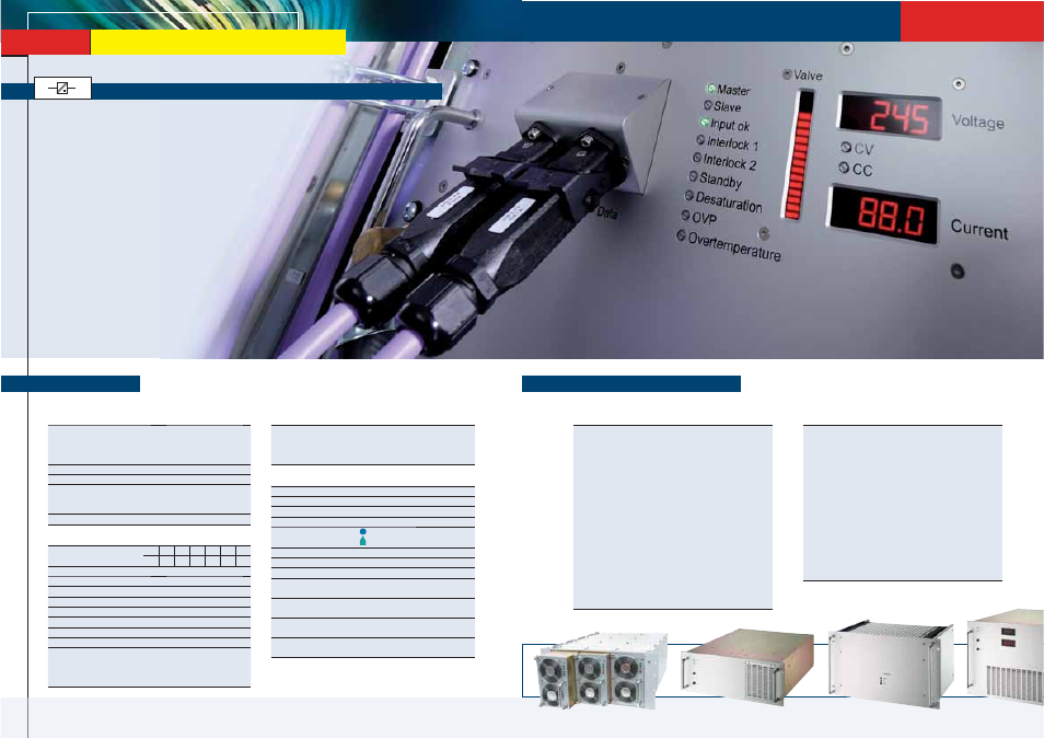
Converters from 5 to 40kW, switchmode
Converters from 5 to 40kW, switchmode
High Power
DC / DC Converters, AC / DC Power Supplies & Battery Chargers
■
DC Input voltage: from 80 - 800V DC
■
AC Input voltage: 115 / 230V AC, single phase or
200 / 400 / 480V AC, three phases
■
AC Input frequency: 47 - 400Hz
■
Output voltage: 5 / ... / 800V DC
■
Output current: up to 800A
■
Output power: 5 - 40kW
Specifications
AC
or
DC
DC
■
Input / Output isolation
■
Continuous short circuit protection
■
Overvoltage protection
■
Thermal shutdown with auto-restart
■
Operational from – 40 to +75 °C
■
Industrial grade components
■
High efficiency through ZVS topology
■
High power density
■
Compact and robust design
■
Fan or liquid cooled
Features
Input
Voltage range
narrowing of input voltage range
optimizes the efficiency (pls.
specify); unit switches off at
under- and overvoltage
No-load input power
30W typical
Switch-on time
<1s typical
Inrush current
3-phase AC input: limited by
thermistor (except for
series 55
xx,
64xx, 66xx, 67xx & CW/BW56xx)
Immunity
acc. to EN 61000-6-2
Output
DC output voltages
5
9
12
15
24
28
48
60 110 200 220 400 600 800
Output power
from 5 to 40kW
Line regulation (±10%)
0.1%
Load regulation (10-90%)
0.2%
Load transient (10-90-10%) 6 % typical
Response time to ±1 %
10 ms typical
Turn-on rise time
Soft-start, 300 ms typical
Ripple
≤ 1% + 30 mV p-p
Overload protection
current limited to 105-110% of I
nom
Overvoltage protection
OVP switches off module with
automatic return to operation;
after 5 seconds, the unit will
remain latched off
Remote sense
standard for all series up to 150 V
output, except for battery chargers;
up to 10 % of U
nom
for output < 60
VDC, up to 6 V for output > 60 VDC
General
Efficiency
80 - 95% typical
Operating temperature
-20 to +75°C optional: -40 to +75°C
Load derating
2.5%/°C above + 55°C
Storage temperature
-40 to + 85°C
Cooling
(details see page 131)
= fan cooled
= liquid cooled
Humidity
up to 95 % RH, non-condensing
Temperature coefficient
0.02 % / °C typical
Safety / Construction
acc. to EN 60950-1 / EN 50178
Protection category
(built-in module)
IP20 acc. to EN 60529,
NEMA or others upon request
EMI
acc. to EN 61000-6-4,
class A, optionally class B
MTBF
approx. 70,000h @ 40°C
acc. to MIL - HDBK - 217E (notice 1)
Connectors
(details see page 132)
terminals / bolts / bars
or CombiTacs for Series 5100
Options (details see page 115)
Input
■
Inrush current limiting
■
Reverse polarity protection for DC input
Output
■
Decoupling diode for redundant / parallel operation
■
Active current sharing for parallel operation
■
Remote on / off (inhibit)
■
Reducing of current limiting at high ambient temperature
Signals
via relay contacts
■
Power ok (input)
■
DC ok (output)
Monitoring
of input / output voltage or current via
■
analog signal
■
interface card RS232 or CAN Bus
Programming
of output voltage or current via
■
potentiometer
■
analog signal
■
interface card RS232 or CAN Bus
Programming of battery chargers
■
Temperature compensated charging voltage
■
Automatic / manual selection of charging characteristic
Mechanics / environment:
■
Wall mount
■
Digital or analog V- and A-meter
■
Increased mechanical strength
■
Tropical protection
■
Extended temperature range to –40 °C