Calibration – Johnson Level & Tool Mfg. 40-6640 User Manual
Page 12
12
©2007 Johnson Level & Tool
Calibration
Re-calibration can be performed as described below.
1. Use a level to mark a horizontal reference line on the wall.
2. Power on the unit to compare the projected horizontal line with the
reference line.
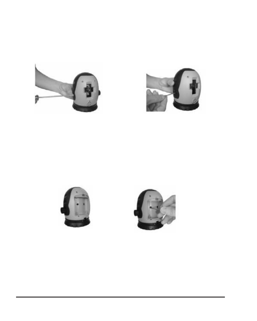
3. If the projected laser line is tilted, power off the unit and lock the compen-
sator. Screw off the calibration portal screw (figure 1) Use a 3mm hex head
wrench to calibrate the unit through its side calibration hole. Insert the hex
head wrench into the instrument and into the calibration screw. Turn the
3mm hex head wrench until the projected line is level. (figure 2) Turn the
hex head wrench clockwise if the line tilts to the right and counter-clock-
wise if the line tilts to the left.
4. If the horizontal line is too high or too low take off the rubber plugs behind
the rechargeable batteries (figure 3). Using a 3mm hex head wrench turn
the calibration screws, moving one screw at a time, clockwise to lower
the line and counter-clockwise to raise the line. Adjust the line to the cor-
rect height (figure 4).
Figure 1
Figure 2
Figure 3
Figure 4