Thermolec Split|Steam User Manual
Page 4
1.4
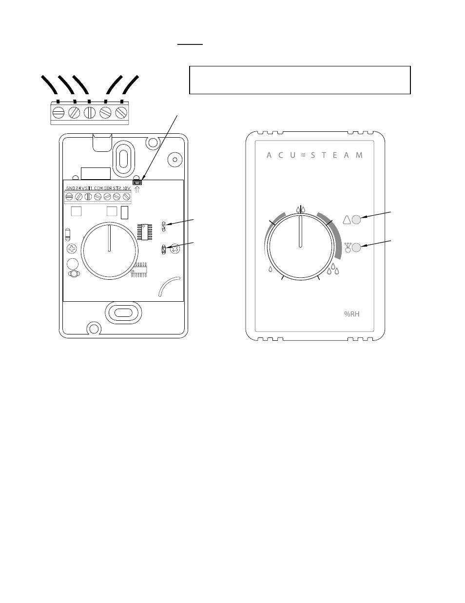
A two wire control cable is required to connect the outdoor sensor to the terminals marked COM & ODR
on the electronic humidistat. Please see Fig. 1d. The outdoor sensor is not polarized so there is no wiring
polarity to follow.
IMPORTANT : Whenever an outdoor sensor is connected to the electronic humidistat, the jumper located at
the top of the electronic board must be removed so that the outdoor sensor becomes operational (i.e.
the jumper short circuits the terminals dedicated to the outdoor sensor). If the outdoor sensor is not installed,
keep the jumper in place.
1.5
To force a drain cycle when the humidifi er is running and producing steam, simply turn down the
humidistat. Please note that when using an ACU-STEAM electronic humidistat, if the relative humidity is
extremely low the humidifi er may still run with the knob at the minimum setting because of a range limiter
inside the cover. If this occurs you will need to remove the humidistat cover by pulling it off and turn the knob
counter-clockwise to the minimum setting. The humidifi er should now stop and drain.
Jumper - MUST be removed when outdoor sensor is connected
- remains in place if the outdoor sensor is not used
GND 24V ST1 COM ODR
Fig. 1d
Red LED - Warning light, flashes when abnormal conditions occur
Green LED - Lit when humidistat is calling for humidity
Red
LED
Green
LED
To Humidifier
Baseplate
Frontplate
From Outdoor Sensor
GND 24V ST1
GND 24V
IN
COM ODR
Red
LED
Green
LED
!
35
30
20
40
50
GND 24VST1 COM ODR ST2 10V