Thermolec Mini Make Up Air User Manual
Page 5
Fan specifi cations
To convert CFM to liters/second multiply CFM value by 0.47.
Electrical installation
Disconnect all power sources before opening the control box and working within. Please conform to all local
and national electrical codes for wiring. The system should be supplied by a separate cable, of appropriate
gauge, and with appropriate protection. Use only wires suitable for 75ºC. Wires shall be sized accordingly to
the Canadian Electrical Code requirements. All wires must be brought through knock-outs. Install a disconnect
switch close to the unit according to the code unless a disconnect switch is already built into the heater.
To quickly calculate the heater amperage use the following formulas:
Single phase
: Amperage = Watts / Voltage.
e.g. 20 kW at 240V would be: 20,000/240 = 83.3 A
Three phase
: Amperage = Watts / (1.732 x Voltage).
e.g. 10 kW at 600V/3 phase would be: 10,000/(1.732 x 600) = 9.6 A
After installing and wiring the system, use the potentiometer on the electronic controller to adjust the desired
temperature and the fan speed control to adjust the air volume. The fan speed should be adjusted according to
the application to compensate for the specifi c static pressure of the installation.
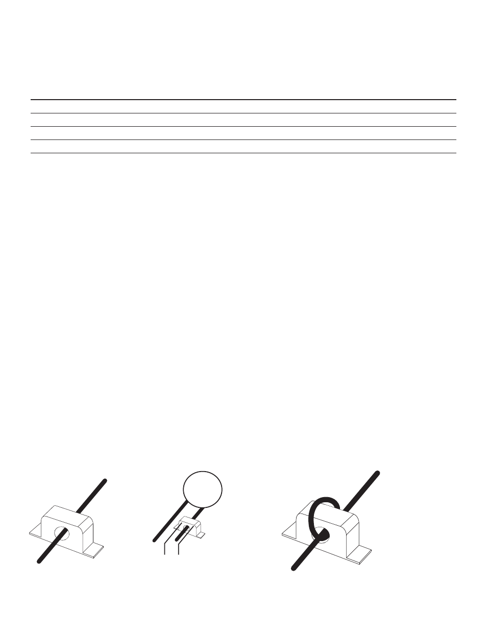
Current sensor instructions
Use the included current sensor to interlock the mini make up air with an exhaust fan. Simply run one of the
power wires of the exhaust fan through the hole in the current sensor (fi g. 7). Some fan amperages may be too
low to switch the current sensor and multiple loops may be required (fi g. 8). Run the fan and test the output of
the current sensor to determine if multiple loops are required. For information on connections refer to the wiring
diagram included with the mini make-up air.
fig.7
CONNECT TO D23-TF ELECTRONIC
CONTROLLER IN UNIT ( T1 & L1 )
EXHAUST
FAN
fig. 8
Unit size
CFM @ 0
VA
C
Hertz
Power (W)
dBA
Max
Amb. T
emp C
Bearing T
y
pe
6”
collar
263
115
50/60
46
60
70
Ball
8”
collar
607
115
50/60
80
61
75
Ball
10”
collar
607
115
50/60
80
61
75
Ball
12”
collar
1100
115
60
175
73
50
Ball
Note: All data as supplied from fan manufacturer.