En g l is h english – Pfister R89-8MBY User Manual
Page 3
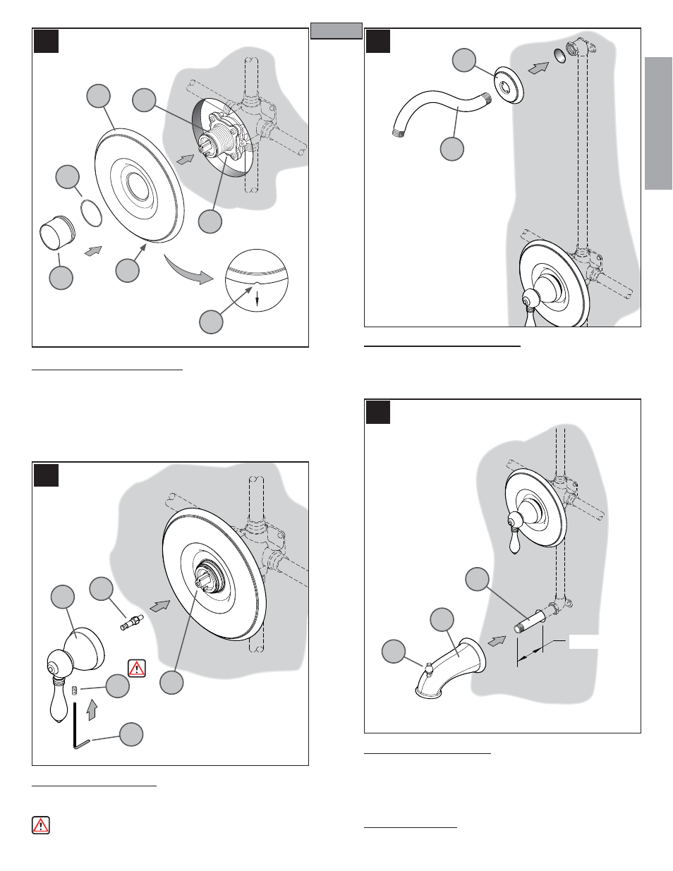
7 TRIM FLANGE ATTACHMENT
Position Flange (7A) on Valve (7B) with Drain Hole (7C) at the bottom. Place
Protective Washer (7D) on the short end of the reversible Retainer Sleeve (7E).
Screw Retainer Sleeve (7E) onto threaded section of the Stem and Bonnet (7G).
Tighten Retainer Sleeve (7E) by hand until Flange (7A) is snug to fi nished wall
surface. If the short end of the Retainer Sleeve (7E) is too short, reverse it to
use the longer end.
8 HANDLE ATTACHMENT
Screw Stem Extender (8A) onto the Valve Stem (8B). Thread the Set Screw (8C)
into the Handle (8D) and thread it in only three to four turns. Place Handle (8D)
onto the Stem Extender (8A) and tighten the Set Screw (8C) by using the Hex
Wrench (8E) that is provided.
Make sure Set Screw (8C) is securely tightened to handle (8D).
10 SPOUT INSTALLATION
Apply PTFE plumbers tape on both ends of Pipe Niple (10A) (not included).
Screw Pipe Niple (10A) into the elbow inside the wall and tighten with pipe
wrench. The Pipe Niple (10A) is to project 3
7
/
8
" to 4" from the fi nished wall.
Screw Tub Spout (10B) onto Pipe Niple (10A) and tighten until Spout is properly
positioned and fl ush to the fi nished wall.
11 UNIT START UP
Turn on hot and cold water supplies, and check all connections for leaks.
9 SHOWER ARM INSTALLATION
Insert the long end of Shower Arm (9A) through the Shower Flange (9B).
Apply PTFE plumber's tape to both ends of Shower Arm (9A) according to
manufacturer's instructions. Screw long end of Shower Arm (9A) into pipe elbow
inside the wall. Slide Shower Flange (9B) tight to the wall.
7
8
9
10
3
ENGLISH
E
N
G
L
IS
H
ENGLISH
7A
8A
9A
7B
7C
7C
7D
7E
7G
8B
8C
8D
8E
9B
10A
3
7
/8” to 4”
10B
10C