Airvantage servicing - power generation module, Exp view – Versa-Matic 3 Clamped Metallic Hazardous Service Ball Valve (RE3) User Manual
Page 23
re3mdlAsmATEXC-rev0614
www
.
versamatic
.
com
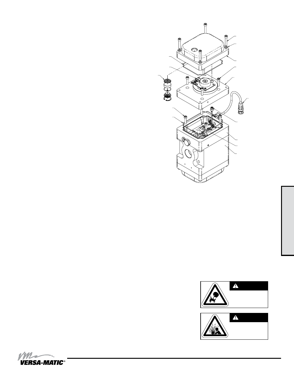
3: EXP
VIEW
Model RE3 Metallic Clamped •
20
AirVantage Servicing - Power Generation Module
To service the power generation module, first shut off and
bleed the air being supplied to the pump. For safety purposes
the air supply line should be disconnected from the pump.
Then shut off the suction and discharge lines to the pump.
Bleed the pressure from the pump suction and discharge lines
and remove the lines from the pump. During the servicing of
the AirVantage, consult the “AirVantage Composite Repair
Parts Drawing”.
Step #1: Remove the Patch Cable
Twist the ribbed portion of the patch cable connector
in a counterclockwise direction, until it unthreads from
the connector. The cable can then be removed from the
intermediate..
Step #2: Remove the AirVantage from the Pump
Use a ½” socket and remove the four 5/16-18 x 5 1/2 cap
screws that hold the AirVantage to the pump. Remove the two
chamber bolts/nuts that are holding the right side bracket to be
able to remove the right bracket and AirVantage unit from the
pump. Be sure to support the weight of the AirVantage while
removing the last cap screw. After the AirVantage is removed
from the pump, set the unit down on the cover located on the
top. Inspect the o-ring between the poppet valve
and the adapter plate for damage.
Step #3: Access the Power Generation Module
Use a 5mm hex-key wrench and loosen the four M6 x 35mm
socket head cap screws securing the bottom cover. Lift the
bottom cover off, exposing the power generation module.
There is a molded o-ring seal located on the underside of the
cap. Make sure the o-ring stays located within the groove.
If the power generation module needs to be replaced, unplug
the connector that connects the power generator to the control
board. Use a 4mm hex-key wrench to loosen the four M5 x
25mm socket head cap screws. The power generation module
should now be loose. Carefully lift the power generation
module off the rest of the assembly, making sure that the
control board wire and connector slips through the hole in
the power generation case.
"AirVantage Caution" - Take caution not to loosen the
o-ring that seals between the components.
Step #4: Reinstallation
When reinstalling the new module make sure to feed the
control module wire through the hole in the power generation
case. Install the four M5 x 25mm socket head cap screws and
tighten to 6.8 N-M.
“AirVantage Caution” – Be sure to reattach the connector
from the power generator to the control board.
Reinstall the bottom cover, making sure the o-ring seal is still
in the groove. Tighten the four M5 x 25mm socket head cap
screws to 3.4 N-M.
Reinstall the top cover, making sure the o-ring seal is still in the
groove. Tighten the four M6 screws. Reinstall the AirVantage
right bracket, chamber bolts/nuts and four 5/16-18 x 5 1/2 cap
screws, torque to 90 in-lbs.
“AirVantage Caution” – Be sure to reattach the patch cable
connector that connects the AirVantage module to the
intermediate.
Note: Refer to Composite Repair Parts
List on page 23 for part numbers
VALVE, POPPET
CONTROL MODULE
CASE, POWER GENERATOR, ATEX
CAPSCREW, HEX SOC HD
M6 X 1.0 X 35
COVER
SEAL, O-RING
SEAL, O-RING
O-RING
CAPSCREW, HEX SOC HD
M6 X 1.0 X 25
CAPSCREW, HEX SOC HD
M6 X 1.0 X 25
CONNECTOR (Power
Generation Module to
Control Module)
CONNECTOR
(Control Module to Power
Generation Module)
CONNECTOR
(To Intermediate)
BREATHER
ASSEMBLY
WASHER, FLAT, M6
Do not open when an
explosive atmosphere
may be present.
WARNING
S u b s t i t u t i o n o f
components may
impair intrinsic safety.
WARNING
Note: Ensure all mating faces are free from scores or damage prior to
re-assembly. Check each metallic face joint with a 0.003" feeler gage
to ensure all flange faces are fully closed after assembly. Failure to do
so may compromise the flameproof design of the assembly.