Parts list – Versa-Matic AP50 SUBMERSIBLE CENTRIFUGAL PUMP User Manual
Page 5
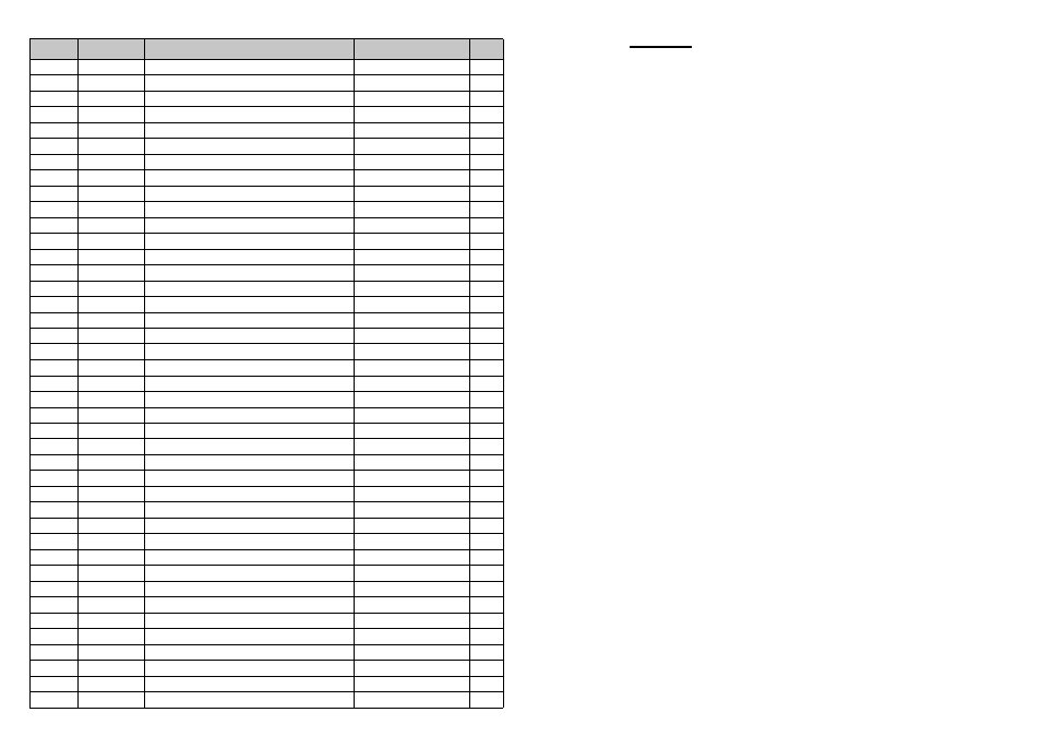
PARTS LIST
REF No
PART No.
DESCRIPTION
MATERIAL
QTY
1
AP50.60
STRAINER
S.G. IRON
1
2
AP50.55
VOLUTE
CAST IRON
1
3
AP50.57
IMPELLER
GUNMETAL
1
4
AP50.56
VOLUTE SHIM (0.010”)
PLASTIC
A/R
5
AP50.56A
VOLUTE SHIM (0.015”)
PLASTIC
A/R
6
AP50.52
SEAL
NBR/ST.STEEL
2
7
A135
HEX. HEAD BOLT - M10 x 25
HT. STEEL
4
8
AP50.51
BEARING HOUSING
CAST IRON
1
9
AP50.43
BUSH
MANGANESE BRONZE
1
10
AP50.42
BEARING NUT
STEEL PLATED
1
11
AP50.41
BEARING
STAINLESS STEEL
1
12
AP50.80
NAMEPLATE
BRASS
1
13
K076
HAMMERDRIVE SCREW - No6 x 3/16
STEEL PLATED
2
14
AP50.67
HANDLE
M.S. TUBE
1
15
A063
HEX. HEAD BOLT - M10 x 40
HT. STEEL
2
16
AP50.44
INTERMEDIATE SECTION
CAST IRON
1
17
AP50.33
LOWER BEARING PLATE
GUNMETAL
1
18
AP50.20A
DOWEL
HT. STEEL
4
19
AP50.25A
LOCATING SCREW
HT. STEEL
1
20
AP50.20
CYLINDER BODY
S.G. IRON
1
21
AP50.25
CYLINDER LINER
CAST IRON
1
22
AP50.29
ROTOR SHAFT
HT. STEEL
1
23
AP50.28
ROTOR KEY
KEY STEEL
1
24
AP50.13
FELT PLUG
FELT
1
25
AP50.15
ADJUSTING SCREW
HT. STEEL
1
26
AP50.09
LOCKSCREW
HT. STEEL
1
27
AP50.22
UPPER BEARING PLATE
GUNMETAL
1
28
AP50.23
CIRCLIP
HT. STEEL
1
29
AP50.19
LOWER GOVENOR SECTION
STEEL
1
30
AP50.18
BALL CAGE
ACETAL
1
31
AP50.17
GOVENOR BALL
STEEL
2
32
AP50.72
THRUST PAD
STEEL
1
33
AP50.07A
GOVENOR VALVE BALL
CARBIDE STEEL
1
34
AP50.04
GOVENOR CYLINDER
BRASS
1
35
AP50.05
O-RING
NITRILE
1
36
AP50.11
OIL FILLER PLUG
STEEL
1
37
AP50.12
WASHER
FIBRE
1
38
AP50.03
SPRING SPIGOT
BRASS
1
39
AP50.02
AIR FILTER
STAINLESS STEEL
1
40
AP50.207
HOSE UNION - NPT
STEEL
1
41
Z128
BLANKING PLUG
PVC
1
Pump Body
3.9 Remove governor housing and air motor as previously described.
Remove bolts (7) from volute (2) and lift pump body assembly
free.
3.10 Turn pump body over, lock impeller and remove nut (81) together
with impeller (3) from intermediate section (16).
3.11 Remove bolts (76) and withdraw bearing housing assembly (8)
from intermediate section (16).
3.12 Turn impeller shaft (74) and check for ease of movement and
quality of impeller bearing (11). Replace bearings as required.
3.13 To replace bearing (11), remove circlip (7) and withdraw impeller
shaft (74) from housing (8). Unscrew impeller nut (10) and
withdraw bearing (11).
3.14 Check impeller seals (75) and o-ring (6) for wear or damage,
replace as required. Ensure correct position of seals (75) so that
lips face the impeller.
3.15 If impeller is damaged or excessively worn, performance of the
pump will be reduced. When replacing, the impeller must be
adjusted to within 0.005" to 0.010" from the volute (2) internal
face for maximum efficiency. This is achieve by the addition or
subtraction of shims (4) & (5).
3.16 Re-assemble the pump as described above in reverse order. Ensure
all fittings are tight and secure before running the pump.