Val-Matic 2-42 Sure Seal Foot Valve User Manual
Page 3
2
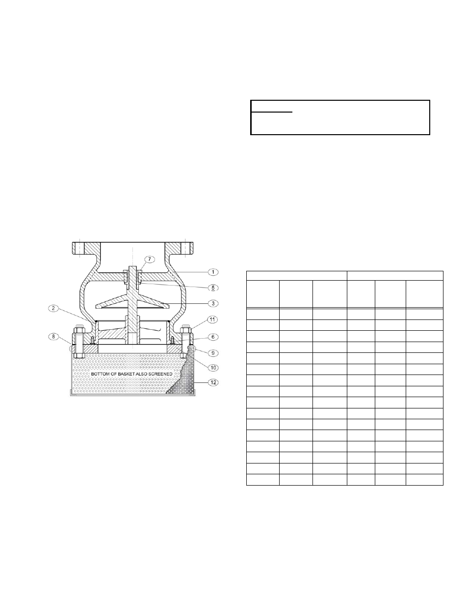
VALVE CONSTRUCTION
The standard Series 1900 Foot Valve is constructed
of rugged cast iron with a bronze or stainless steel
trim. See the specific Materials List submitted for
the order if other than standard cast iron
construction. The details of construction are
illustrated in Figure 2.
The body (1) is furnished with a flanged outlet for
bolting to the suction piping. The body is equipped
with a bronze seat (2). The disc (3) is guided by a
bronze bushing (7) fixed in the body. Leak-tight
closure is made when the resilient seal located (6) is
compressed by the closed disc. A stainless steel
basket assembly (12) prevents debris from entering
the valve.
The only moving parts in the valve are the plug and
spring. The body bushing controls the movement of
the plug and assures that the plug contacts the seat
evenly. The valve has a resilient seal for drop tight
service.
FIGURE 2. FOOT VALVE CONSTRUCTION
INSTALLATION
The installation of the valve is important for its
proper operation. Some general recommendations
follow.
The flow direction is vertical flow up. Orient the
valve so that the basket is in the wet well or water
source. The basket lower surface should be at least
.75 times the valve diameter from the bottom of the
wet well floor or consult the pump manufacturer for
direction.
CAUTION: DO NOT INSTALL THE VALVE IN
HORIZONTAL PIPING OR SLAMMING MAY
RESULT.
The valve should be mated to ANSI Class 125# flat-
faced flanges equipped with resilient gaskets. When
ring gaskets are used, the bolt material shall be
ASTM A307 Grade B or SAE Grade 2 Carbon Steel.
Higher strength bolts may only be used with full-face
gaskets.
Lower valve into line using slings or chains around
the valve body. Lubricate the flange bolts or studs
and insert them around the flange. Lightly turn bolts
until gaps are eliminated. Recommended lubricated
torques for use with resilient gaskets (75 durometer)
are given in Table 1.
The torquing of the bolts should then be done in
graduated steps using the cross-over tightening
method. If leakage occurs, allow gaskets to absorb
fluid and check torque and leakage after 24 hours.
Do not exceed bolt rating or crush gasket more than
50 per cent of its thickness.
125# FLANGE DATA
250# FLANGE DATA
Valve
Size
(in)
Bolt
Dia.
(in)
Bolt
Torque
(ft-lbs)
Valve
Size
(in)
Bolt
Dia.
(in)
Bolt
Torque
(ft-lbs)
2.5 5/8
25-75
2.5 3/4
25-75
3 5/8
25-75
3 3/4
35-75
4 5/8
30-90
4 3/4
50-150
5 3/4
30-90
5 3/4
70-150
6 3/4
30-90
6 3/4
70-150
8 3/4
40-120
8 7/8
90-200
10 7/8
45-150
10 1
110-300
12 7/8
65-200
12 1
1/8
160-450
14 1
80-250
14 1
1/8
140-450
16 1
90-300
16 1
1/4
180-600
18 1
1/8
100-350
18 1
1/4
190-600
20 1
1/8
120-450
20 1
1/4
220-600
24 1
1/4
150-500
24 1
1/2
350-900
30 1
1/4
180-600
30 1
3/4
500-1500
36 1
1/2
250-750
36 2
700-2000
42 1
1/2
300-900
42 2
800-2500
TABLE 1. FLANGE BOLT TORQUES
C CAUTION:
Mating flanges must be flat faced
or damage to the valve may
result.