Val-Matic Surgebuster Check Valve User Manual
Page 3
2
Table 1. Flange Bolts Torques
Valve Bolt Recom. Max.
Size Dia Torque Torque
(in) (in) (ft-lbs) (ft-lbs)
3
5/8
25
90
4
5/8
25
90
6
3/4
30
150
8
3/4
40
150
10
7/8
45
205
12
7/8
65
205
14
1
80
300
16
1
80
300
18
1 1/8
100
425
20
1 1/8
100
425
24
1 1/4
150
600
30
1 1/4
160
600
36
1 1/2
300
900
42
1 1/2
300
900
48
1 1/2
300
1,000
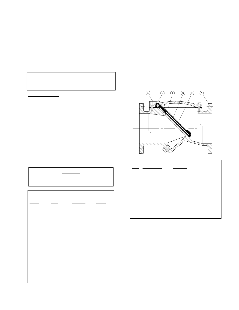
Item Description Material
1
Body
Ductile Iron – 250 psi
Cast Iron – 150 psi
2
Cover
Ductile Iron – 250 psi
Cast Iron – 150 psi
3
Disc*
Steel With Buna-N Facing
4
Cover Seal* Buna-N or Non-Asbestos
5
Cover Bolt Alloy Steel
13 Accelerator Stainless Steel
*Recommended Spare Part
INSTALLATION
Correct installation of the Surgebuster
is
important for proper operation. It may be installed
in either horizontal or vertical flow-up applications.
However, when horizontal, the valve must be
installed with the nameplate facing up and the
cover level. In all installations, the flow arrow cast
in the valve cover must be pointed in the direction
of flow during normal system operation.
FLANGED ENDS: Flanged valves can be mated
with raised or flat-faced pipe flanges equipped with
full-face or ring-type resilient gaskets. The valve
and adjacent piping must be supported and
aligned to prevent cantilevered stress on the
valve. Once the flange bolts or studs are
lubricated and inserted around the flange, tighten
them uniformly hand tight. The tightening of the
bolts should then be done in graduated steps
using the crossover tightening method.
Recommended lubricated torque values for use
with resilient gaskets (75 durometer) are given in
Table 1. If leakage occurs, allow gaskets to absorb
fluid and check torque and leakage after 24 hours.
Do not exceed bolt rating or extrude gasket.
VALVE CONSTRUCTION
The standard Surgebuster
Check Valve is
constructed of rugged cast iron with a rubber
encapsulated disc. See the specific Materials List
submitted for the order if other than standard cast
iron construction. The disc is the only moving part
assuring long life with minimal maintenance. The
general details of construction are illustrated in
Figure 2. The body (1) is flanged for connection to
the pipeline with an open top sealed with a cast
cover (2). The disc (3) and disc accelerator (13)
are retained by the cover.
FIGURE 2. CHECK VALVE CONSTRUCTION
MAINTENANCE
The SurgeBuster
Check Valve requires no
scheduled lubrication or maintenance. For service
or inspection, the valve can be serviced without
removal from the line.
VALVE INSPECTION: If inspection of the valve is
required, follow the Disassembly Instructions given
on page 3.
WARNING
Do not use threaded holes in cover for
lifting the valve. Serious injury may result.
CAUTION
The use of ring gaskets or excessive bolt
torque may damage valve flanges.